
Page 58 - ELICYLINDER-EC-IAI, CILINDRI ELETTRICI,
P. 58
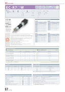
EC ELECYLINDER
EC-R7£W
Water Proof / Dust Proof
Rod Motor IP67 Type Unit Type
Coupled Motor
Body Width 24V 73 Stepper
mm
Motor
¢ Model Specification Items
ECR7W ()
Series
Type Lead
S : 24mm H : 16mm M : 8mm L : 4mm
Dust/Splash-proof
Stroke
50: 50mm
300:300mm (Every 50mm)
Cable Length
0: With terminal block type connector
1:1m 8:8m
Options
Refer to Options below.
* Please refer to P.16 for more information about the model specification items.
Horizontal
Side
Ceiling
* Depending on the model, there may be some limitations to using the vertical, side, and ceiling mount positions. Please contact IAI for more information regarding mounting positions.
Table of Payload by Speed/Acceleration
Lead 24 Lead 16
Orientation
Horizontal
Vertical
0.5
0.5
Orientation
Speed (mm/s)
0.3
Horizontal
1
Vertical
Speed (mm/s)
Acceleration (G)
Acceleration (G)
0.3
0.5
0.7
1
0.3
0.5
0.7
0.3
0
20
18
15
12
3
38
38
37
34
21
0
50
40
35
30
8
200
20
18
15
12
3
140
50
40
35
30
8
400
20
14
12
8
3
280
50
35
25
20
7
420
17
12
10
6
3
420
25
18
14
10
4.5
600
14
6
5
4
3
560
10
5
3
2
2
640
5
3
2
1.5
2
700
2
800
5
1
1
860
2
0.5
Lead 8
1
0.5
18
18
12
Lead 4
Selection Notes
(1) The maximum acceleration/deceleration is 1G for horizontal, and 0.5G for vertical use.
(2) The actuator specifications display the payload's maximum value, but it will vary depending on the acceleration and speed. Please refer to "Table of Payload by Speed/Acceleration" at right for
more details.
(3) The value of the horizontal payload assumes that there is an external guide. Please be aware
that the anti-rotation stopper can be damaged when an external force is applied to the rod
from any direction other than the moving direction.
(4) When performing push-motion operation, refer to P.65.
(5) Depending on the ambient operating temperature, duty control is necessary.
Please refer to P.67 for more information.
(6) The interface box is not dust-proof or splash-proof.
Install in a location not exposed to water.
(7) The power capacity can be reduced according to the setting. Please refer to P.63 for the relevant "Table of Payload by Speed/Acceleration."
Orientation
Horizontal
Vertical
Orientation
Horizontal
Vertical
Speed (mm/s)
Acceleration (G)
Speed (mm/s)
Acceleration (G)
0.3
0.5
0.7
1
0.3
0.3
0.5
0.7
1
0.3
0.5
19
19
19
0
60
50
45
40
18
0
80
70
65
60
19
70
60
50
45
40
18
35
80
70
65
60
19
140
60
50
45
40
16
70
80
70
65
60
19
210
60
40
31
26
10
105
140
80
60
50
40
18
280
34
20
15
11
5
50
30
20
15
12
350
12
4
1
2
175
15
2
Actuator Specifications
¢Lead and Payload ¢Stroke and Max Speed (Unit: mm/s)
Model number
Lead (mm)
Max. payload
Max. push force (N)*
Horizontal (kg)
Vertical (kg)
EC-R7SW-1-2(-3)
24
20
3
182
EC-R7HW-1-2(-3)
16
50
8
273
EC-R7MW-1-2(-3)
8
60
18
547
EC-R7LW-1-2(-3)
4
80
19
1094
Lead (mm)
50~300 (Every 50mm)
24
860<640>
16
700<560>
8
350
4
175
Legend: 1 Stroke 2 Cable Length 3 Option
<> represents vertical operation.
*Speed limitation applies to push motion. See the manual or contact IAI.
1 Stroke
3 Options
2 Cable Length
9 18
4 10
1
1 Stroke (mm)
EC-R7£W
1 Stroke (mm)
EC-R7£W
50
200
100
250
150
300
Cable code
Cable length
0
No cable (with connector)
1~3
1~3m
4~5
4~5m
6~8
6~8m
* Make sure that the total length of the actuator cable and power I/O cable is 10m or less.
Actuator Specifications
(*) The rod tip angular displacement (initial value for reference) when the allowable static torque on rod tip is applied with the rod fully retracted.
Name
Option code
Reference page
Actuator cable length: 5m
AC5
See P.59
Brake
B
See P.59
Flange (front)
FL
See P.59
Foot bracket
FT
See P.60
Tip adapter (internal thread)
NFA
See P.61
Non-motor end specification
NM
See P.62
PNP specification
PN
See P.62
Battery-less Absolute Encoder specification
WA
See P.62
Wireless communication specification
WL
See P.62
Item
Description
Drive system
Ball screw f12mm, rolled C10
Positioning repeatability
±0.05mm
Rod
f30mm Material: Aluminum, hard alumite treatment
Rod tip static allowable torque
0.5N·m
Rod tip maximum angular displacement (*)
±1.5 degrees
Degree of protection
IP67
Ambient operating temperature/humidity
0 to 40°C, 85% RH or less (Non-condensing)
57 EC-R7£W
Vertical
~
~
I
O
N
P
T
