
Page 25 - RoboCilindri, RCP5, robocilindri, sinta,
P. 25
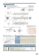
Dimensional DrawingsCAD drawings can be downloaded from the website.www.robocylinder.de2D CAD*1 During home return, be careful to avoid interference from peripheral objects because the slider travels until the mechanical end.*2 The orientation of the width across flats varies depending on the product. *3 If the actuator is installed using the front housing and flange, make surethe actuator will not receive any external force.(For details, refer to “Notes on Installing Rod Actuators” on P. 31.) ME: Mechanical endSE: Stroke endDimensions with Brake (Optional)Rod Deflection of RCP5-RA8C(The graph below shows the measurements of how much a horizontally installed rod would deflect when a load is applied to the end of the rod. The measured deflection include the deflection due to the weight of the rod.)NoteIf an actuator of lead 5 is installed vertically, the service life of the actuator varies significantly depending on the payload.Pay attention to the diagram of payload and service life shown below. (If the actuator is installed horizontally, its service life is not affected by the payload.)4.0 3.5 3.0 2.5 2.0 1.5 1.0 0.5 0.00Pulse-train type Field network typeWith brakeA 011223344556674 Cable Exit Directions (Optional)Dimensions and Mass by Stroke700st 600st 500st 400st 300st 200st 100st HomeB C D115 65 115 65 115 65 115 65 115 65 115 65 115 65 4 6 6 8 8 10 10 12 12 14 14 16 16 18LStrokeWithout brake50 100 150 439.5 489.5 539.5 488 538 588200 250 589.5 639.5 638 688300 350 400 450 500 550 600 650 700 689.5 739.5 789.5 839.5 889.5 939.5 989.5 1039.5 1089.5 738 788 838 888 938 988 1038 1088 1138Dimensions with Flange (Optional)Deflection (mm)50Load at end of rod (N)Applicable Controller150 20010.0 10.4 10.9 11.3100RCP5 series actuators can be operated with the controller indicated below. Select the type according to your intended application.NamePositioner typeExternal viewModel numberPCON-CFA-60PWAI-NP- -0- PCON-CFA-60PWAI-PN- -0-FeaturesPositioner type based on PIO controlMaximum number of positioning points512 pointsInput powerDC24VPower supply capacityPCON-CFA-60PWAI-PLN- -0- PCON-CFA-60PWAI-PLP- -0-Allowable static load at end of rod (N)Allowabledynamic Load offset 0mm loadat endof rod(N) Load offset 100mmAllowable static torque at end of rod (Nm) Allowable dynamic torque at end of rod (Nm) Mass (kg) Without brakeWith brake180 73.6 57.0 18.1 5.7 7.1 8.3150.3 128.9 112.7 60.3 51.0 44.1 48.6 42.5 37.8 15.2 13.0 11.4 9.7 8.5 7.5 7.6 8.0 8.4 8.7 9.1 9.699.9 89.7 81.3 74.3 38.7 34.3 30.7 27.7 33.8 30.5 27.6 25.2115 165 215 265 315 365 415 465515 565 615 68.3 63.1 58.6 25.2 22.5 17.7 23.1 21.2 17.7 7.1 6.6 6.1 4.6 4.2 3.9 10.6 11.0 11.4 11.7 12.1 12.6665 715 765 54.6 51.1 47.9 14.2 11.6 9.5 14.2 11.6 9.5 5.8 5.4 5.1 3.6 3.3 3.0 11.9 12.3 12.7 13.0 13.4 13.9Reference pageRefer to P. 39Refer to P. 46 * In the model numbers shown above, indicates the field network specification (DV, CC, PR, CN, PRT, EC or EP).PCON-CFA-60PWAI--0-0-Pulse-train input type Supporting major field networks— 768 points10.2 9.2 6.7 6.0 8.9 9.38.4 7.7 5.5 5.0 9.7 10.224
