
Page 140 - RoboCilindri, RCP4, robocilindri, sinta,
P. 140
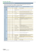
PCON-CB/CFB ControllerThe table below lists the signal assignments for the at cable in the pulse-train control mode.Connect an external device (such as PLC) according to this table.I/O power supply +24VDi erential pulses are input from the host. Up to 200kpps can be input. The servo is ON while this signal is ON, and OFF while the signal is OFF.Home return operation is performed when this signal is turned ON.The actuator is forcibly stopped when this signal has remained ON for 16ms or more. The actuator decelerates to a stop at the torque set in the controller and the servo turns OFF.The brake is forcibly released.When this signal turns on, the actuator moves to the reference position set in parameter No.167. *1: Used only in PIO Pattern 7.Not usedNot usedNot usedThis signal turns ON when the controller becomes ready after the main power supply has been turned on.This signal turns ON when the amount of remaining travel pulses in the deviation counter falls within the in-position band.This signal turns ON upon reaching the torque limit while the torque is limited.This signal turns ON when the emergency stop of the controller is cancelled, and turns OFF when an emergency stop is actuated.An alarm code is output when an alarm generates. For details, refer to the operation manual.This signal turns ON when movement to the reference point set in parameter No. 167 is completed. *1: Used only in PIO Pattern 7.Di erential pulses are input from the host. Up to 200kpps can be input.I/O power supply 0VI/O power supply 0VNote) # indicates a negative logic signal. Negative logic signals are normally ON while the power is supplied, and turn OFF when the signal is output.I/O Signals in Pulse-train Control ModePin number1A2A3A4A5A6A7A8A9A10A11A12A13A14A15A16A17A18A19A20A1B2B3B4B5B6B7B8B9B10B11B12B13B14B15B16B17B18B19B20BCategory24V24VPulseInputInputOutputPulseInput0V0VI/O numberIN0IN1IN2IN3IN4IN5IN6IN7IN8IN9IN10IN11IN12IN13IN14IN15OUT0OUT1OUT2OUT3OUT4OUT5OUT6OUT7OUT8OUT9OUT10OUT11OUT12OUT13OUT14OUT15Signal abbreviationP24P24PP/PPSONRESHOMETLCSTPDCLRBKRLRMODRSTR*1NCNCNCNCNCNCNCPWRSVINPHENDTLR#ALM#EMGSRMDSALM1ALM2ALM4ALM8#ALMLREND*1ZONE1ZONE2NP/NPNNSignal namePower supplyPower supplyDi erential pulse-train input (+)Di erential pulse-train input (-)Servo ONResetHome returnTorque limit selectionForced stopDeviation counter clearForced brake releaseOperation mode switchingReference position movement command-------System readyServo ON statusPositioning completeHome return completeTorque limitedController alarm statusEmergency stop statusOperation mode statusAlarm code output signalMinor failure alarmReference position movement completeZone signal 1Zone signal 2Di erential pulse-train input (+)Di erential pulse-train input (-)Power supplyPower supplyI/O power supply +24VParameter No.25, “PIO pattern 6/7”Present alarms are reset when this signal is turned ON.139 PCON-CB/CFBWhen this signal is turned ON, the motor torque is limited to the value set by the parameter.This signal clears the deviation counter.The operation mode can be switched when the MODE switch on the controller is set to AUTO.(AUTO when this signal is OFF, and to MANU when the signal is ON.)Not usedNot usedNot usedNot usedThis signal turns ON when the servo is ON.This signal turns ON upon completion of home return.This signal turns ON when the controller is normal, and turns OFF when an alarm generates.The operation mode status is output. This signal turns ON when the controller is in the manual mode.This signal turns ON when the controller is normal, and turns OFF when a message-level alarm has been generated.This signal turns ON when the current position of the actuator falls within the parameter-set range.
