
Page 28 - RoboCilindri, RCP4, robocilindri, sinta,
P. 28
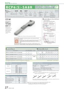
RCP6 RoboCylinderRCP6(S)-SA8R±10μ m StandardSimple Battery- Motor Dust- less Unit proof Absolute CoupledBody Width24VPulse MotorSide-mounted Motor85* mm Model Speci cation ItemsSeriesSA8R WAType Encoder Type56SPMotor Type56SP: High-thrust Pulse Motor56SizeLead30: 30mm 20: 20mm 10: 10mm 5: 5mmStroke50: 50mm1100: 1100mm (50mm increments)Applicable Controller/I/O Type[RCP6]P4: PCON-CFB/CGFB [RCP6S]SE: SIO Type* Body width does not include the width of the side- mounted motor.N : NoneP : 1mS : 3mM:5mX : Speci ed Length when ordering the side- R : Robot Cable mounted motor type.Cable LengthOptionsRCP6: Separate Controller RCP6S: Built-in ControllerWA: Battery-less AbsolutePlease refer to the options table below.* RCP6 does not include a controller. RCP6S includes a built-in controller.* Please make sure to specifyeitherMLorMRHorizontal Side Correlation Diagrams of Speed and Payload PCON connected.RCP6(S)-SA8R Horizontal mountLLead 5 assumes operation at 0.1G, the other leads assume operation at 0.3G.ead565 Lead 10Lead20Lead 30 1444Ceiling100 90 80 70 60 50 40 30 20 10 00*Depending on the model, there may be some limitations to using the vertical, side, and ceiling mount positions. Please contact IAI for more information regarding mounting positions.800 1000 1200 1400 Speed (mm/s)200 400 600ad 5Lead 5 assumes operation at 0.1G, the other leads assume operation at 0.3G.LeThe gure above is the motor side-mounted to the left (ML).RCP6(S)-SA8R Vertical mount 6050 40 30 20 1000 200 400 600 800 1000 1200 1400 Speed (mm/s)Selection Notes(1) The maximum acceleration/deceleration is 1G for horizontal, and 0.5G for vertical use.(2) The actuator speci cation displays the payload's maximum value, but it will vary depending on the acceleration and speed. Please refer to the "Selection Guidelines" (RCP6 Tables of Payload by Speed/Acceleration) on P.115 for more details.(3) When performing push-motion operation, please con rm the push force of each model by checking the "Correlation diagram of push force and current limit" on P.113.Actuator Speci cationsLead and Payload Stroke and Max. Speed (Unit: mm/s)Legend: Stroke Applicable controller/I/O type Cable length Options Values in brackets < > are for vertical use.Model NumberLead (mm)Max. PayloadStroke (mm)Horizontal (kg)Vertical (kg)RCP6(S)-SA8R-WA-56SP-30----3026350~1100 (The incrementof stroke is 50mm)RCP6(S)-SA8R-WA-56SP-20----20554RCP6(S)-SA8R-WA-56SP-10----107025RCP6(S)-SA8R-WA-56SP-5----58055Lead (mm)50~650 (Every 50mm)700 (mm)750 (mm)800 (mm)850 (mm)900 (mm)950 (mm)1000 (mm)1050 (mm)1100 (mm)301200 <850>1155 <850>1040 <850>940 <850>855 <850>780715660201000 <800>950 <800>860 <800>77069563057052048044010500 <450>480 <450>4303853453102852602352205250240215190175155145130120110Cable Length* Refer to P.144 for more information regarding the maintenance cables.OptionsActuator Speci cationsItemDescriptionDrive systemBall screw ø16mm, rolled C10Positioning repeatability±0.01mmLost motion0.1mm or lessBaseMaterial: Aluminum with white alumite treatmentStatic allowable momentMa: 219N•m, Mb: 219N•m, Mc: 414N•mDynamic allowable moment (*1)Ma: 77.0N•m, Mb: 77.0N•m, Mc: 146N•mAmbient operating temp. & humidity0~40°C, 85% RH or less (Non-condensing)Cable TypeCable CodeStandardP (1m)S (3m)M (5m)Speci ed LengthX06 (6m) ~ X10 (10m)X11 (11m) ~ X15 (15m)X16 (16m) ~ X20 (20m)Robot CableR01 (1m) ~ R03 (3m)R04 (4m) ~ R05 (5m)R06 (6m) ~ R10 (10m)R11 (11m) ~ R15 (15m)R16 (16m) ~ R20 (20m)(*1) Assumes a standard rated life of 5000km. The service life will vary depending on operation and installation conditions.• Reference for overhang load length: Ma: 400mm or less, Mb, Mc: 400mm or less Allowable load moment directions Overhang load lengthsMa Mb Mc Ma L McPlease refer to the RoboCylinder General Catalog for more information regarding the directions of the allowable moment and overhang load length.(*1) Slider spacer option cannot be selected together with the double slider option.(*2) This option is not available with some combination of the leads and mounting positions. Please refer to P.131 for more information.NameOption CodeReference PageBrakeBSee P.105Cable exit direction (Outside)CJOSee P.105Motor side-mounted to the leftMLSee P.109Motor side-mounted to the rightMRSee P.109Non-motor end speci cationNMSee P.110Slider spacer (*1)SSSee P.111Slider roller speci cationSRSee P.111Double slider (*2)WSee P.112L27 RCP6(S)-SA8RLeadLe 2210ad 2 0.500.51 Lead 30Payload (kg) Payload (kg)Vertical~IONPT
