
Page 37 - RoboCilindri, RCP4, robocilindri, sinta,
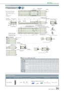
P. 37
DimensionsCAD drawings can be downloaded from our website. www.robocylinder.de*1 When the slider is returning to its home position, please be careful of interference from surrounding objects, as it will travel until it reaches the M.E.2D CAD110 90 402002-φ8H7 reamed, depth 8 8-M8 depth 24.5RCP6 RoboCylinder Must be 100or more(1.5)Motor unit* It is possible to mount the motor unit at 180 degree rotated.3236.57175 49.53239 3.3 5.8140+0.015 8022.86 38.5 (0.5)1 71 336.1 36.5134 (φ8H7 pitch: ±0.02)M.E: Mechanical end S.E: Stroke endposition for allowable moment calculationL169 (Without brake) 229 (With brake)Reference surface(123) 1 158160 (Base width)Q (n/a for 50&100mm strokes)Q (n/a for 50&100mm strokes) N±0.02 (n/a for 50&100mm strokes)Grease nipple (both sides)100±0.02 (n/a for 50&100mm strokes)Applicable Controllers156 (Slider width) 150118AP-φ8H7 reamed From base mounting surface depth 99100 J×100 pitchK-φ9 through -φ16.5 counterbored (From opposite side)φ9Details of base mounting partR-oblong hole From base mounting surface depth 9RCP6S-WSA16C199 (Without brake) 229 (With brake)Status LED55 Must be 100 or moreMotor unit* It is possible to mountthe motor unit at 180 degree rotated.G (H)445 M.E.S.E.55StrokeT-slot : M3 (Both sides)Home572 M.E.6156 (Motor unit width) 35 62-M3 depth 6 (For ground line)3 1.3Side T-slot details156 (Motor unit width) 6 27.1 6Teaching portConnector for power supply /I/O cable connection25Cable exit direction (Option)CJT TopMassStrokeRCP6 w/obrakew/brake RCP6S w/obrakew/brake2-M3 depth 6 (For ground line)CJL LeftCJR RightDimensions and Mass by Stroke5555R-oblong hole From base mounting surface depth 9 P-φ8H7 reamed From base mounting surface depth 925CJT TopCJB BottomCJB Cable exit direction (Option) Bottom50 100 150 200 250 300 350 400 450 500 550 600 650 700 750 800 850 900 950 1000 1050 1100 535 585 635 685 735 785 835 885 935 985 1035 1085 1135 1185 1235 1285 1335 1385 1435 1485 1535 1585 595 645 695 745 795 845 895 945 995 1045 1095 1145 1195 1245 1295 1345 1395 1445 1495 1545 1595 1645 565 615 665 715 765 815 865 915 965 1015 1065 1115 1165 1215 1265 1315 1365 1415 1465 1515 1565 1615 595 645 695 745 795 845 895 945 995 1045 1095 1145 1195 1245 1295 1345 1395 1445 1495 1545 1595 1645 366 416 466 516 566 616 666 716 766 816 866 916 966 1016 1066 1116 1166 1216 1266 1316 1366 1416- - 100 100 100 100 100 100 100 100 100 100 100 100 100 100 100 100 100 100 100 100 158 208 58 108 58 108 58 108 58 108 58 108 58 108 58 108 58 108 58 108 58 108 0 0 1 1 2 2 3 3 4 4 5 5 6 6 7 7 8 8 9 9 10 10 4 4 8 8 10 10 12 12 14 14 16 16 18 18 20 20 22 22 24 24 26 26 - - 100 100 100 100 100 100 100 100 100 100 100 100 100 100 100 100 100 100 100 100RCP6 w/obrake 8.7 9.3 9.9 10.5 11.1 11.7 12.3 12.9 13.4 14.0 14.6 15.2 15.8 16.4 17.0 17.6 18.1 18.7 19.3 19.9 20.5 21.1 w/brake 9.6 10.1 10.7 11.3 11.8 12.4 13.0 13.5 14.1 14.7 15.2 15.8 16.3 16.9 17.5 18.1 18.6 19.2 19.7 20.3 20.9 21.4 (kg) RCP6S w/obrake 8.9 9.5 10.1 10.7 11.2 11.8 12.4 13.0 13.6 14.2 14.8 15.4 15.9 16.5 17.1 17.7 18.3 18.9 19.5 20.1 20.6 21.2 w/brake 9.6 10.2 10.7 11.3 11.9 12.5 13.0 13.6 14.1 14.7 15.3 15.8 16.4 17.0 17.5 18.1 18.7 19.2 19.8 20.4 20.9 21.5LAGHJKNP 1122222222222222222222 Q - - 208 258 308 358 408 458 508 558 608 658 708 758 808 858 908 958 1008 1058 1108 1158 R 0011111111111111111111The RCP6 series actuators can be operated by the controllers indicated below. Please select the type depending on your intended use. * Please refer to P.147 for more information about the built-in controller of RCP6S series.Name External Max. number of view controlled axesPCON-CFB/CGFB 1Input powerDC24VControl methodMaximum number Reference page of positioning points512 Please see P.132 (768 for network spec.)Positioner Pulse train Program - *Option *OptionNetwork *OptionCJL LeftCJR RightRCP6(S)-WSA16C 36
