
Page 82 - RoboCilindri, RCP4, robocilindri, sinta,
P. 82
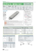
RCP6 RoboCylinder RCP6(S)-WRA14CBattery- Motor less Unit Absolute CoupledBody Width24VPulse Motor Model Speci cation ItemsWRA14C WASeries Type Encoder Type56PMotor Type56P: Pulse Motor56SizeLead24: 24mm 16: 16mm 8: 8mm 4: 4mmStroke50: 50mm600: 600mm (50mm increments)Applicable Controller/I/O Type[RCP6] P3: PCONMCONMSEL [RCP6S]SE: SIO TypeCable LengthOptionsRCP6: Separate Controller RCP6S: Built-in ControllerWA: Battery-less AbsoluteN : NoneP : 1mS:3mM:5mX : Speci ed Length R : Robot CablePayload (kg) Payload (kg)(*) For high output setting to OFF refer to the RCP6 manual.Vertical~* RCP6 does not include a controller. RCP6S includes a built-in controller.Radial Load OK Correlation Diagrams of Speed and Payload High-output enabled (*) with PCON/MCON/MSEL connected. RCP6(S)-WRA14C Horizontal mountHorizontal Side*Depending on the model, there may be some limitations to using the vertical, side, and ceiling mount positions. Please contact IAI for more information regarding mounting positions.Selection Notes100 90 80 70 60 50 40 30 20 1000Lead 415Lead 4/8 assumes operation at 0.1G, the other leads assume operation at 0.3G.Lead 8 Lead 16CeilingStraight Motor140 mmPlease refer to the options table below.IONPTActuator Speci cations (*)Lead and PayloadModel Number(*) For values of disabled high output controller setting refer to the RCP6 manual.(1) The maximum acceleration/deceleration is 1G for horizontal, and 0.5G for vertical use.25 20 15 105Lead 4Lead 8 9This graph assumes 7operation at 0.3G.(2) The actuator speci cation displays the payload's maximum value, but it will vary depending on the acceleration and speed. Please refer to the "Selection Guidelines" (RCP6 Tables of Payload by Speed/Acceleration) on P.115 for more details.(3) The radial cylinder is equipped with a built-in guide. Please refer to the graphs shown in P.127 and after for the allowable load mass.(4) When performing push-motion operation, please con rm the push force of each model by checking the "Correlation d i a g r a m o f p u s h f o r c e a n d c u r r e n t l i m i t " o n P. 1 1 3 .(5) Depending on the ambient operational temperature, duty control is necessary for the RCP6S (built-in controller type) with lead 4/8/16. Please refer to P.130 for more information.00 100 200 300 400 500 600 700 800 Speed (mm/s)RCP6(S)-WRA14C-WA-56P-24---- 24RCP6(S)-WRA14C-WA-56P-16---- 16RCP6(S)-WRA14C-WA-56P-8---- 8RCP6(S)-WRA14C-WA-56P-4---- 4Legend: Stroke Applicable controller/I/O type Cable length Options-- 15 25630 560Cable LengthCable Type StandardSpeci ed LengthCable Code P (1m)S (3m)M (5m)X06 (6m) ~ X10 (10m) X11 (11m) ~ X15 (15m) X16 (16m) ~ X20 (20m) R01 (1m) ~ R03 (3m) R04 (4m) ~ R05 (5m) R06 (6m) ~ R10 (10m) R11 (11m) ~ R15 (15m) R16 (16m) ~ R20 (20m)Actuator Speci cationsItem Drive systemPositioning repeatabilityLost motionRodRod non-rotation precision (*) Allowable load and torque on rod tip Rod tip o set/overhang distance Ambient operating temp. & humidityValues in brackets < > are for vertical use.Description Ball screw ø12mm, rolled C10±0.01mm0.1mm or lessø40mm Stainless steel0 deg.See P. 129dx: 150mm or less / dz: 100mm or less 0~40°C, 85% RH or less (Non-condensing)Robot Cable* Refer to P.144 for more information regarding the maintenance cables.(*) Rod's angular displacement in rotational direction with no load applied to the rod.OptionsName BrakeCable exit direction (Top) Cable exit direction (Right) Cable exit direction (Left) Cable exit direction (Bottom) FlangeNon-motor end speci cation T-slot nut bar (Left)T-slot nut bar (Right)Option CodeB CJT CJR CJL CJB FL NM NTBLNTBRReference Page See P.105 See P.105 See P.105 See P.105 See P.105 See P.106 See P.110 See P.110 See P.110O set distance at end of rod (dx: 150mm or less)Load at end of rodOverhang distance at end of rod (dz: 100mm or less)Load at end of rod81 RCP6(S)-WRA14C(**) The payload assumes that there is an external guide. Stroke and Max. Speed(Unit: mm/s)600 (mm)395 <210>195 <130>Lead (mm)Connected Max. Payload Controller Horizontal(kg)(**) Vertical(kg)Stroke (mm)50~600 (The incrementof stroke is 50mm)Lead Connected (mm) Controller24 High-output Enabled16 High-output EnabledHigh-output 8 Enabled4 High-output Enabled50~550 (Every 50mm)420 <210>210 <130>High-output 25 EnabledHigh-output 50 EnabledHigh-output Enabled 65High-output 85 Enabled1007 Speed (mm/s)Lead24 6 8600 700 800200 300400500RCP6(S)-WRA14C Vertical mount 30
