
Page 85 - RoboCilindri, RCP4, robocilindri, sinta,
P. 85
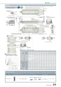
DimensionsCAD drawings can be downloaded from our website. www.robocylinder.deφ8H7 reamed, depth 8 4-M8 depth 12Details of rod tipReamed hole at the end of the ange*2 The misalignment against 5 the base reference: ±1° M.E.2D CADStroke (65.5)RCP6 RoboCylinder*1 When the rod is returning to its home position, please be careful of interference from surrounding objects, as it will travel until it reaches the M.E. M.E: Mechanical end S.E: Stroke end45°φ60h7 height 1610 7145.53232140φ62h7 φ45 (Rod outer diameter)+0.015 8069.513.323 328.580 45.510 7145.1 45.58125.5 40 623φ24H7 depth 8P.C.D.46Reference 1 surface2-M3 depth 6 (For ground line)2-φ8H7 reamed From base mounting surface depth 9 (1 hole only for 50mm stroke)100200100st 200st300Load on rod tip (N)6007004-M10 depth 15 85(123)158160 (Base width)6RCP6S-WRA16CMust be 100 or more 2525CJT TopCJB BottomP-φ8H7 reamed From base mounting surface depth 9 R-oblong hole From base mounting surface depth 94545N±0.02 (n/afor 50,100,150mmstrokes) 459100 J×100 pitchCJR Right199 (Without brake) 229 (With brake)6 Teaching port156 (Motor unit width) 27.1 6Rod De ection of RCP6(S)- WRA16C (Reference Values)G H J K N P Q75 125 0111122334455667 4 6 6 8 8 10 10 12 12 14 14 16 16 18 18 204.0 3.5 3.0 2.5 2.0 1.5 1.0 0.5 0.0075 125 75 125 75 125 75Applicable ControllersName External Max. number of view controlled axesPCON-CFB/CGFB 1Input powerDC24VControl methodMaximum number Reference page of positioning points512 Please see P.132 (768 for network spec.)400500300st 600st 400st 700st 500st 800stRCP6 (kg) RCP6Sw/o brake w/ brake w/o brake w/ brake22.8 23.9 23.3 24.5 23.0 24.1 23.5 24.625.1 26.2 27.3 28.5 25.6 26.7 27.9 29.0 25.2 26.3 27.5 28.6 25.8 26.9 28.0 29.1Status LEDConnector for power supply/ I/O cable connection2-M3 depth 6 (For ground line)S.E.35 Home M.E.169 (Without brake) 199 (With brake)unit at 180 degree rotated.156 (Motor unit width) 35 6Cable exit direction (Option) * It is possible to mount the motor unit at 180 degree rotated.Motor unitCJL LeftCJL LeftCJR Right*2 When the overhang is large or severe adjustment of the angleis required, please attach the ttings without using the reamed hole.Must be 100 or moreQ (n/a for 50&100mm strokes)Q (n/a for 50&100mm strokes)100±0.02 (n/a for 50mm stroke)R-oblong hole From base mounting surface depth 96.8 5Side T-slot detailsφ9Details of base mounting partG(H)CJT TopCJB BottomK-φ9 through -φ16.5 counterbored 45 (From opposite side)Dimensions and Mass by StrokeLStrokeRCP6 w/o brakew/ brake RCP6S w/o brakew/ brake A50 100 150 446 496 546 476 526 576 476 526 576 506 556 606 277 327 377 --- 125 75 125200 596 626 626 656 427 100 75250 300 350 646 696 746 676 726 776 676 726 776 706 756 806 477 527 577 100 100 100 125 75 125400 450 796 846 826 876 826 876 856 906 627 677 100 100500 550896 946 996 1,046 1,096 1,146 1,196 926 976 1,026 1,076 1,126 1,176 1,226 926 976 1,026 1,076 1,126 1,176 1,226 956 1,006 1,056 1,106 1,156 1,206 1,256 727 777 827 877 927 977 1,027 100 100 100 100 100 100 100100st200st300st400st500st600st R--- 100 100 100 100 100 100 100 100 100 100 100 100 100 1112222222222222 - - 175 225 275 325 375 425 475 525 575 625 675 725 775 825 0011111111111111 588 588 588 511 451 402 362 329 300 275 254 235 217 202 188 176Allowable static load on rod tip (N) 700st40 40 255 220 3,000kmloadonrodtip(N) Loado set100mm 133 133 Allowabledynamictorqueonrodtip(N•m) 20.0 20.0 Allowable dynamic Load o set 0mm 214 184 5,000kmloadonrodtip(N) Loado set100mm 133 13340 40 40 191 168 149 133 133 133 20.0 20.0 20.0 160 140 124 133 124 112 20.0 18.6 16.8 13.7 14.9 16.0 14.3 15.4 16.5 13.9 15.0 16.2 14.4 15.5 16.740 40 40134 120 109122 111 10118.3 16.7 15.2111 99 89101 91 83 75 68 62 56 50 45 40 36Allowable static torque on rod tip (N•m) 800st40 40 40 40 40 40 40 40 99 90 81 74 67 61 55 50 92 84 77 70 64 58 53 48 13.8 12.6 11.5 10.5 9.6 8.7 7.9 7.1 80 72 65 59 53 47 42 37MassAllowable dynamic Load o set 0mmAllowabledynamictorqueonrodtip(N•m)20.0 20.0 11.5 12.6 12.0 13.1 11.6 12.7 12.1 13.315.2 13.7 17.1 18.3 17.6 18.8 17.3 18.4 17.8 18.912.4 11.3 10.2 19.4 20.5 21.7 19.9 21.1 22.2 19.5 20.7 21.8 20.1 21.2 22.39.2 8.4 7.5 6.8 6.0 5.3L AT-slot : M8 (both sides)* Can be used when the actuator is side mounted.(1.5)Motor unit* It is possible to mount the motorThe RCP6 series actuators can be operated by the controllers indicated below. Please select the type depending on your intended use. * Please refer to P.147 for more information about the built-in controller of RCP6S series.Positioner Pulse train Program - *Option *OptionNetwork *OptionGrease nippleCable exit direction (Option)600 650 700750 800RCP6(S)-WRA16C 84
