
Page 69 - RoboCilindri, Controller, robocilindri, sinta,
P. 69
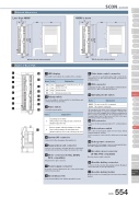
1 2 3 456 7 89 1011 1213 1415 16171 LED displayThese LED colors indicate the condition of the controller.9 Pulse train control connectorThis connector is used during pulse train control mode operations. It is disconnected during operations in positioner mode.10 PIO connectorConnector for the cable for parallel communicationswith the PLC and other peripheral devices. 11 Operating mode switchName ExplanationMANU Do not receive PIO commandsAUTO Accept PIO commands*The emergency stop switch on the teaching pendant becomes effective when the line is connected, regardless of whether this switch is set to AUTO or MANU. Take note that an emergency stop will be actuated momentarily when the teaching-pendant or SIO communication cable is disconnected. This is a normal phenomenon and does not indicate an error.12 SIO connectorConnector for the teaching pendant or PC communicationscable.13 Brake release switchThis is the electromagnetic brake forced release switch,integrated with the actuator.*It is necessary to connect the DC 24V power for the brake drive.14 Brake power connectorBrake power DC 24V supply connector (only required whenthe brake equipped actuator is connected)15 Encoder sensor connector (X-SEL-P/Q compatible)Encoder sensor cable connector16 Absolute battery connectorConnector for the absolute data backup battery. (Requiredonly for absolute encoder specifications)17 Absolute battery holderBattery holder for installing the absolute data backup batteryExternal dimensionsSCON ControllerSliderType MiniStandardControllers IntegratedRod TypeMiniStandardControllers IntegratedTable/Arm /FlatTypeMiniStandardGripper/ Rotary TypeLinear Motor TypeCleanroom TypeSplash-ProofControllersPMEC /AMECPSEP /ASEPROBO NETERC2 PCON ACON SCON PSEL ASEL SSEL XSELPulse MotorServo Motor (24V)Servo Motor (230V)Linear MotorLess than 400W400W or more2958(80)1214372(80)121ø4.2ø4.25 184 1945 184 194(200.5)(200.5)4.24.2Name of Each PartWith the absolute battery installedWith the absolute battery installedName ColorExplanationLit when the system is ready (after power is ON, CPU normal functions)Lit when servo is ONLit during an alarmLit during an emergency stopPWR SV ALM EMGGreen Green Orange Red2 Rotary switchThis is the address setting switch for identifying eachcontroller when they are linked.3 Piano switch Controller system switch.Name12ExplanationOperating mode switchOFF: positioner mode ON: pulse train control mode *Enabled at power ON.Remote update switch (normally set to OFF) OFF: normal operating mode ON: update mode *Enabled when power is ON or during soft reset.4 System I/O connector Connector for the emergency stop switch etc.5 Regeneration unit connector Connector for resistance unit that absorbs regenerationcurrent produced when the actuator decelerates to a stop.6 Motor connector (X-SEL, ECON, RCS compatible)Actuator motor cable connector.7 Power supply connectorAC power connector. Divided into the control power inputand motor power input.8 Grounding screwProtective grounding screw. Always ground this screw.SCON 554
