
Page 75 - RoboCilindri, Controller, robocilindri, sinta,
P. 75
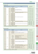
PSEL ControllerMiniStandardControllers IntegratedMiniStandardControllers IntegratedMini StandardExplanation of I/O Signal FunctionsProgram modePin NumberClassificationPort No.Program ModeFunctions1A P24 1B2A2B3A 3B 4A 4B 5A 5B 6A 6B7A Input 7B8A 8B 9A 9B 10A 10B 11A 11B 12A 12B 13A 13B 14A 14B15A Output 15B16A16B17A17B N016 017 018 019 020 021 022 023 000 001 002 003 004 005 006 007 008 009 010 011 012 013 014 015 300 301 302 303 304 305 306 30724V inputSelect Program No. 1 Select Program No. 2 Select Program No. 4 Select Program No. 8 Select Program No. 10 Select Program No. 20 Select Program No. 40 CPU resetStart General-purpose input General-purpose input General-purpose input General-purpose input General-purpose input General-purpose input General-purpose input General-purpose input General-purpose input General-purpose input General-purpose input General-purpose input General-purpose input General-purpose input General-purpose input AlarmReady General-purpose output General-purpose output General-purpose output General-purpose output General-purpose output General-purpose output 0V inputResets the system to the same state as when the power is turned on. Starts the program selected by ports 016 to 022.Waits for external input via program instructions.Turns off when an alarm occurs. (Contact B)Turns on when the controller starts up normally and is in an operable state.These outputs can be turned ON/OFF as desired via program instructions.Connect 0V.Connect 24V.Selects the program number to start. (Input as BCD values to ports 016 to 022)*Note: With regard to PNP wiring diagram, please refer to PSEL manual.0V 24NPN* Wiring DiagramPMEC /AMECPSEP /ASEPROBO NETERC2 PCON ACON SCON PSEL ASEL SSEL XSELPositioner mode1A P24 1B2A2B3A 3B 4A 4B 5A 5B 6A 6B7A Input 7B8A 8B 9A 9B 10A 10B 11A 11B 12A 12B 13A 13B 14A 14B15A Output 15B16A16B17A17B N016 017 018 019 020 021 022 023 000 001 002 003 004 005 006 007 008 009 010 011 012 013 014 015 300 301 302 303 304 305 306 30724V inputPosition input 10 Position input 11 Position input 12 Position input 13Error resetStartHome return Servo ONPushPauseCancel Interpolation settings Position input 1 Position input 2 Position input 3 Position input 4 Position input 5 Position input 6 Position input 7 Position input 8 Position input 9 AlarmReady Positioning complete Home return complete Servo ON output Pushing complete System battery error0V inputResets minor errors. (Severe errors require a restart.)Starts moving to selected position. Performs home return.Switches between Servo ON and OFF. Performs a push motion.Pauses the motion when turned OFF, and resumes when turned ON.Stops the motion when turned OFF. The remaining motion is canceled. When this signal is turned ON for a 2-axis model, the actuator moves by linear interpolation.Specifies the position numbers to move to, using ports 007 to 019. The number can be specified either as BCD or binary.Turns off when an alarm occurs. (Contact B)Turns on when the controller starts up normally and is in an operable state. Turns on when the movement to the destination is complete.Turns on when the home return operation is complete.Turns on when servo is ON.Turns on when a push motion is complete.Turns on when the system battery runs low (warning level).Connect 0V.Pin NumberClassificationPort No.Positioner Standard ModeFunctions*Note: With regard to PNP wiring diagram, please refer to PSEL manual.0V 24Connect 24V.Specifies the position numbers to move to, using port number 007 to 019. The number can be specified either as BCD or binary.NPN* Wiring DiagramPSEL 560Slider TypeRod TypeTable/Arm /Flat TypeGripper/ Rotary TypeLinear Motor TypeCleanroom TypeSplash-ProofControllersPulse MotorServo Motor (24V)Servo Motor (230V)Linear Motor
