
Page 34 - ELICYLINDER-EC-IAI, CILINDRI ELETTRICI,
P. 34
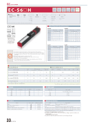
EC ELECYLINDER EC-S6£H
High
Rigidity Type
Motor Unit Type
Body Width
24V
Stepper Motor
¢ Model Specification Items
ECS6H ()
Slider
Coupled Motor
63 mm
Series
Type Lead
S : 20mm H : 12mm M : 6mm L : 3mm
High Rigidity
Stroke
50: 50mm
400:400mm (Every 50mm)
Cable Length
0: With terminal block type connector
1: 1m 10:10m
Options
Refer to Options below.
Vertical
~
~
* Please refer to P.16 for more information about the model specification items.
Horizontal Side
Ceiling
* Depending on the model, there may be some limitations to using the vertical, side, and ceiling mount positions. Please contact IAI for more information regarding mounting positions.
Table of Payload by Speed/Acceleration
Lead 20
Orientation
Speed (mm/s) 0.3
Horizontal Vertical Acceleration (G)
Lead 12
Orientation
Horizontal Acceleration (G)
Speed
0.5 0.7 1 0.3 0.5 (mm/s) 0.3 0.5 0.7 1
0.3 0.5 2.5 2.5 2.5 2.5 2.5 2.5 2.5 2.5 2.5 2.5 2.5 2.5
Vertical
0 160 320 480 640 800
Lead 6
Orientation
Speed (mm/s) 0.3
I
O
N
P
T
Selection Notes
(1) The maximum acceleration/deceleration is 1G for horizontal, and 0.5G for vertical use.
(2) The actuator specifications display the payload's maximum value, but it will vary depending on the acceleration and speed. Please refer to "Table of Payload by Speed/Acceleration" at right for
more details.
(3) When performing push-motion operation, refer to P.65.
(4) Depending on the ambient operating temperature, duty control is necessary.
Please refer to P.67 for more information.
(5) The power capacity can be reduced according to the setting. Please refer to P.63 for the
6 6 6 6 6 6 6 6 6 6 6 5.5 5 4.5
12.5 12.5 12.5 12.5 12.5 12.5 12.5 12.5 12.5 12.5 12.5 12 10 9
6
relevant "Table of Payload by Speed/Acceleration."
86422
0 40 100 160 220 280 340 400 450
32 32 32 32 32 32 32 22 15
26 24 20
26 24 20
26 24 20
26 24 20
26 24 20
26 24 15
20 18 12
12 1183.53.5
0 40 50 40 80 40 110 40 140 40 170 40 200 35 225 28
250 300 (mm) (mm)
35 35 35 35 35 32 28 20
35 35 35 35 35 30 35 30 35 28 32 24 23 20 16 12
15 15 12 12 12 10
10 8 7 1 1 10 8 7 1 1 10 8 6 1 1 9 8 6 1 1 8 6 5 1 1 6.5 4.5 3 1 1
Horizontal Vertical Orientation Horizontal Vertical Acceleration (G) Speed Acceleration (G)
0 26 80 26 200 26 320 26 440 26 560 20
18 16 14 18 16 14 18 16 14 18 14 12 18 12 10 12 87
700 1595 421
Lead 3
0.5 0.7 1 0.3 0.5 (mm/s) 0.3 0.5
0.7 1 0.3 0.5
Actuator Specifications
¢Lead and Payload Model number
EC-S6MH-1-2(-3) 6 32 6 185 6 450 364 261 EC-S6LH-1-2(-3) 3 40 12.5 370 3 225 184 131
EC-S6SH-1-2(-3)
Lead (mm)
Max. payload Horizontal (kg) Vertical (kg)
Max. push Lead force (N)* (mm)
50~200 (Every 50mm)
20
EC-S6HH-1-2(-3) 12 26 2.5 93 12 700 513
15 1
56 20
800
¢Stroke and Max Speed
(Unit: mm/s)
350 400 (mm) (mm)
717 559 386 301 196 152 98 76
Legend: 1 Stroke 2 Cable Length 3 Option 1 Stroke
*Speed limitation applies to push motion. See the manual or contact IAI.
Cable length
No cable (with connector) 1~3m
4~5m
6~10m
1 Stroke (mm)
50 100 150 200
3 Options Brake
Non-motor end specification
PNP specification
Battery-less Absolute Encoder specification Wireless communication specification
1 Stroke (mm)
250 300 350 400
Option code
B NM PN WA WL
2 Cable Length Cable code
0 1~3 4~5 6~10
Actuator Specifications
EC-S6£H
EC-S6£H
Reference page See P.59 See P.62 See P.62 See P.62 See P.62
33 EC-S6£H
Name
Item Drive system
Positioning repeatability Base
Allowable static moment Allowable dynamic moment (*) Ambient operating temperature/humidity
Description Ball screw f10mm, rolled C10
±0.05mm
Material: Aluminum, black alumite treatment
Ma direction: 48.5N·m, Mb direction: 69.3N·m, Mc direction: 103N·m Ma direction: 33.7N·m, Mb direction: 40.2N·m, Mc direction: 55.3N·m 0 to 40°C, 85% RH or less (Non-condensing)
· Overhang load length guideline: 300mm or less
(*) For reference rated life of 5,000km. The service life differs according to operation conditions and
mounting status.
Contact IAI to check the service life.
Contact IAI to check the allowable moment direction and overhang load length.
