
Page 36 - ELICYLINDER-EC-IAI, CILINDRI ELETTRICI,
P. 36
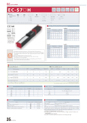
EC ELECYLINDER EC-S7£H
High
Rigidity Type
Motor Unit Type
Body Width
24V
Stepper Motor
Slider
Coupled Motor
75 mm
¢ Model Specification Items
ECS7H ()
Series
Type Lead
S : 24mm H : 16mm M : 8mm L : 4mm
High Rigidity
Stroke
50: 50mm
500:500mm (Every 50mm)
Cable Length
0: With terminal block type connector
1: 1m 10:10m
Options
Refer to Options below.
Vertical
~
~
* Please refer to P.16 for more information about the model specification items.
Horizontal Side
Ceiling
* Depending on the model, there may be some limitations to using the vertical, side, and ceiling mount positions. Please contact IAI for more information regarding mounting positions.
Table of Payload by Speed/Acceleration
Lead 24
Lead 16
Vertical (mm/s) 0.3 0.5 0.7 1 0.3 0.5 (mm/s) 0.3 0.5 0.7 1 0.3 0.5
Orientation Speed
Horizontal Vertical Acceleration (G)
Orientation
Horizontal Acceleration (G)
0 200 420 640 860
Lead 8
Orientation
37 22 37 22 34 20 20 15 12 10
16 14 16 14 16 14 109 74
Speed
3 30 46 35
28 27 28 27 25 24 15 10 10 6 5 3
8 8 8 8 8 8 5 4.5 4 3 3 2
3 3 3 3 3 3 3 2.5
140 46 35 280 46 35 420 34 25 560 20 15 700 15 10
Lead 4
I
O
N
P
T
Selection Notes
(1) The maximum acceleration/deceleration is 1G for horizontal, and 0.5G for vertical use.
(2) The actuator specifications display the payload's maximum value, but it will vary depending on the acceleration and speed. Please refer to "Table of Payload by Speed/Acceleration" at right for
more details.
(3) When performing push-motion operation, refer to P.65.
(4) Depending on the ambient operating temperature, duty control is necessary.
Please refer to P.67 for more information.
(5) The power capacity can be reduced according to the setting. Please refer to P.63 for the
0 51 45 70 51 45 140 51 40 210 51 35 280 40 28
40 40 40 40 38 35 30 24 20 15
1616 0 51 1616 35 51 1616 70 51 10 9.5 105 51 8 7 140 45
45 45 45 45 35 18
40 40 40 40 40 40 40 35 30 25
19 19 19 19 19 19 19 19 14 12
9 7.5
relevant "Table of Payload by Speed/Acceleration."
350 30 9454175 30 4207 2 2106
¢Stroke and Max Speed
Horizontal Vertical Orientation Horizontal Vertical Acceleration (G) Speed Acceleration (G)
Speed
(mm/s) 0.3 0.5 0.7 1 0.3 0.5 (mm/s) 0.3 0.5 0.7 1 0.3 0.5
Actuator Specifications
¢Lead and Payload Model number
EC-S7SH-1-2(-3)
EC-S7HH-1-2(-3)
EC-S7MH-1-2(-3)
EC-S7LH-1-2(-3)
Legend: 1 Stroke 2 Cable Length 3 Option
Lead (mm)
24 16 8 4
1 Stroke (mm)
300 350 400 450 500
Max. payload
Max. push force (N)*
112 168 336 673
(Unit: mm/s)
450 500 (mm) (mm)
*Speed limitation applies to push motion. See the manual or contact IAI.
Cable length
No cable (with connector) 1~3m
4~5m
6~10m
Horizontal (kg)
37 46 51 51
615 503 392 321 199 163 100 82
Vertical (kg)
3 8 16 19
EC-S7£H
Reference page See P.59 See P.62 See P.62 See P.62 See P.62
Lead (mm)
24 16 8 4
50~300 350 (Every 50mm) (mm)
860
700 626
420 319 210<175> 161
400 (mm)
768
488
248
125
<> represents vertical operation.
1 Stroke 1 Stroke
(mm)
50 100 150 200 250
3 Options Brake
Non-motor end specification
PNP specification
Battery-less Absolute Encoder specification Wireless communication specification
2 Cable Length Cable code
0 1~3 4~5 6~10
Actuator Specifications
EC-S7£H
35 EC-S7£H
Name
Option code
B NM PN WA WL
Item Drive system
Positioning repeatability Base
Allowable static moment Allowable dynamic moment (*) Ambient operating temperature/humidity
Description Ball screw f12mm, rolled C10
±0.05mm
Material: Aluminum, black alumite treatment
Ma direction: 115N·m, Mb direction: 115N·m, Mc direction: 229N·m Ma direction 75.5N·m, Mb direction 90N·m, Mc direction 134N·m 0 to 40°C, 85% RH or less (Non-condensing)
· Overhang load length guideline: 300mm or less
(*) For reference rated life of 5,000km. The service life differs according to operation conditions and
mounting status.
Contact IAI to check the service life.
Contact IAI to check the allowable moment direction and overhang load length.
