
Page 13 - RoboCilindri, RCP5, robocilindri, sinta,
P. 13
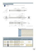
Dimensional DrawingsCAD drawings can be downloaded from the website.www.robocylinder.de2D CADReference planeX*1During home return, be careful to avoid interference from peripheral objects because the slider travels until the mechanical end. ME: Mechanical endSE: Stroke end+ 0.010 3019.812 (1)362448Top face of slider49(1)6.3(1)2.53.525Detail view of X25 1526.5 39 40LStroke 76(56)Home124 (without brake) 155 (with brake )Range of 56 or morePay attention to interference (Applicable Controller98.5M3, depth 4 (Same on opposite side) (For ground line)H7 reamed, depth 4F-Ø3.4, throughØ6.5 counterbored, depth 3.5 (from opposite side)M-M4, through(Bolt screw-in depth: 5 mm or less)155 (186)Ø 6.5 Ø 3.424±0.02Must be 100 or more.Referposition for Ma/Mc moments5M.E.M.E.).404Detail Y* The dimensions in ( ) apply when brake is equipped.123S.E.Oblong hole, depth 45035 38H50 (at stroke 50)G x 100 (M4 hole pitch)JRCP5 series actuators can be operated with the controller indicated below. Select the type according to your intended application.NamePositioner typePulse-train typeField network typePosition controller, 8-axis type6-axis type with I/O control functionExternal viewModel numberPCON-CA-35PWAI-NP- -0- PCON-CA-35PWAI-PN- -0-PCON-CA-35PWAI-PLN- -0- PCON-CA-35PWAI-PLP- -0-FeaturesMaximum number of positioning pointsPCON-CA-35PWAI--0-0-MSEP-C--0Equipped with a high-output driver 512 points Positioner type based on PIO controlEquipped with a high-output driver — Pulse-train input typeEquipped with a high-output driver 768 points Supporting major field networksPositioner type that accepts 3 points/256 points connection of up to eight axes.-35PWAI~ - -35PWAI~Axes can be moved and I/O signal turned ON/OFF using a ladder logic program.4-M3, depth 7 20 (Ø3 H7 interval: ±0.02)40 3292-Ø3 H7 reamed, depth 6 Work part installed on the slider Pay attention to interference.ED ×10012 20K20Y 17 17A (Reamed hole pitch)B (Reamed hole and oblong hole pitch)2-Ø3(R1.5)-* In the model numbers shown above, indicates the field network specification (DV, CC, PR, CN, PRT, EC or EP).MSEP-LC-(*) MSEP-LC coming soon with CE conformity.-0- (*)256 pointsC(5)Dimensions and Mass by StrokeLStroke 50 100 Without brake 297 347 With brake 328 378 A50100150 200 397 447 428 478 100 200250 300 497 547 528 578 200 300 185 285350 400 597 647 628 678 300 400 285 385450 500 697 747 728 778 400 500 385 485B 35 85 85C 25 50 50 50 50 50 50 50 50 50D0011223344 E 50 100 50 100 50 100 50 100 50 100 F 8 8 10 10 12 12 14 14 16 16 G-112233445H J K MMass Without brake 1.0 1.1 (kg) With brake 1.2 1.31.3 1.4 1.5 1.5 1.6 1.7Power supply capacityRefer to P. 46Refer to P. 551.6 1.7 1.8 1.8 1.9 2.0Reference pageRefer to P. 39Refer to P. 471851.2 1.3 1.4 1.5Input powerDC24V100 50334 384373 4236 6 6 8 8 10 10 12 12 1450 50 134 184 173 223100 50 234 284 273 323100 50 434 484 473 523100 50 534 584 573 62312
