
Page 15 - RoboCilindri, RCP5, robocilindri, sinta,
P. 15
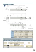
Dimensional DrawingsCAD drawings can be downloaded from the website.www.robocylinder.de2D CADReference plane*1During home return, be careful to avoid interference from peripheral objects because the slider travels until the mechanical end. ME: Mechanical end+0.012 4018.316.546544.5162.5Top face of slider62.5(4.5)5.54.540for Ma/Mc momentsXM3, depth 6 (Same on opposite side) (For ground line)H-Ø4 H7 reamed, depth 5.5 28F-M5, through(Bolt screw-in depth: 9mm or less) D-Ø4.5, throug hØ8 counterbored, depth 4.5(from opposite side )142 (181.5)585Detail Y* The dimensions in ( ) apply when brake is equipped.Applicable ControllerSE: Stroke end60 5021Ø8 Ø4.54-M5, depth 10 31 ( Ø5 H7 interval: ±0.02)32±0.0 22- Ø5 H7 reamed, depth 6Must be 100 or more.Detail view of X40 2317.5 38.5 57 58G-oblong hole, depth 5.5LM.E .10.5S.E.YHom eK 33112.5 (without brake) 152 (with brake)13StrokeAB (Reamed hole and oblong hole pitch)C×10 0 E×100JDimensions and Mass by Stroke11065(Reamed hole pitch) 102830 (M5 hole pitch) 1037.5 M.E. (*1)8(R2)9LStroke Without brakeWith brake ABC50 100 150 200 250 300 350 400 450 500 550 600 650 700 750 800 323 373 423 473 523 573 623 673 723 773 823 873 923 973 1023 1073 362.5 412.5 462.5 512.5 562.5 612.5 662.5 712.5 762.5 812.5 862.5 912.5 962.5 1012.5 1062.5 1112.5 0 100 100 200 200 300 300 400 400 500 500 600 600 700 700 800 0 85 85 185 185 285 285 385 385 485 485 585 585 685 685 785 11223344556677884 4 6 6 8 8 10 10 12 12 14 14 16 16 18 18 00011223344556674 6 6 8 8 10 10 12 12 14 14 16 16 18 18 20 0111111111111111 2333333333333333 172 222 272 322 372 422 472 522 572 622 672 722 772 822 872 922 210.5 260.5 310.5 360.5 410.5 460.5 510.5 560.5 610.5 660.5 710.5 760.5 810.5 860.5 910.5 960.5DEFGHJKMass Without brake3.1 3.2 3.3 3.4Input powerDC24V3.4 3.6 3.8 3.6 3.8 4.0Power supply capacityRefer to P. 46Refer to P. 553.9 4.1 4.3 4.1 4.3 4.5Reference pageRefer to P. 39Refer to P. 471.7 1.8 2.0 2.2 2.4 2.5 2.7 2.9 (kg) With brake 1.9 2.0 2.2 2.4 2.6 2.7 2.9 3.1RCP5 series actuators can be operated with the controller indicated below. Select the type according to your intended application.NamePositioner typePulse-train typeField network typePosition controller, 8-axis type6-axis type with I/O control functionExternal viewModel numberPCON-CA-42PWAI-NP- -0- PCON-CA-42PWAI-PN- -0-PCON-CA-42PWAI-PLN- -0- PCON-CA-42PWAI-PLP- -0-PCON-CA-42PWAI--0-0-FeaturesMaximum number of positioning pointsMSEP-C--42PWAI~ -42PWAI~- -0Equipped with a high-output driver 512 points Positioner type based on PIO controlEquipped with a high-output driver — Pulse-train input typeEquipped with a high-output driver 768 points Supporting major field networksPositioner type that accepts 3 points/256 points connection of up to eight axes.MSEP-LC-(*) MSEP-LC coming soon with CE conformity.256 pointsAxes can be moved and I/O signal turned ON/OFF using a ladder logic program.- -0- (*)* In the model numbers shown above, indicates the field network specification (DV, CC, PR, CN, PRT, EC or EP).6514
