
Page 17 - RoboCilindri, RCP5, robocilindri, sinta,
P. 17
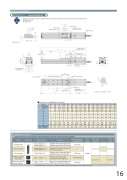
Dimensional DrawingsCAD drawings can be downloaded from the website.www.robocylinder.de2D CADReference plan e*1During home return, be careful to avoid interference from peripheral objects because the slider travels until the mechanical end. ME: Mechanical endSE: Stroke endReferfor Ma/Mc momentsØ9.5 Ø613 4834-M5, depth 106050 32±0.0 20L11060(Reamed hole pitch) 302-Ø5 H7, depth 1 0Part installed on the slider Pay attention to interference.+ 0.012 4021. 328.517. 5 146.5(7)645Top face of slider71(7)5.55.548Detail view of X(72)30X 26.5 53.5 7273M.E. S.E.Home56372 M.E. (*1)Range of 72 or morePay attention to interference.13.5G-oblong hole, depth 63M3, depth 6 (Same on opposite side) 73 (For ground line)39 ( Ø5 H7 interval:Stroke±0.02)K2(5)143(without brake) 193(with brake )Must be 100 or more.(R2)Applicable ControllerNamePositioner typePulse-train typeField network typePosition controller, 8-axis type6-axis type with I/O control functionExternal viewModel numberPCON-CA-56PWAI-NP- -0- PCON-CA-56PWAI-PN- -0-PCON-CA-56PWAI-PLN- -0- PCON-CA-56PWAI-PLP- -0-PCON-CA-56PWAI--0-0-FeaturesMaximum number of positioning pointsMSEP-C--56PWAI~ -56PWAI~- -0Equipped with a high-output driver 512 points Positioner type based on PIO controlEquipped with a high-output driver — Pulse-train input typeEquipped with a high-output driver 768 points Supporting major field networksPositioner type that accepts 3 points/256 points connection of up to eight axes.YAB (Reamed hole and oblong hole pitch)C×10 04045 30H-Ø4 H7 reamed, depth 6 5 40E×100 9J60(M5 hole pitch)F-M5, depth 9D-Ø6, throughØ9.5 counterbored, depth 5.5 (from opposite side)195 (245)Detail Y*The dimensions in ( ) apply when brake is equipped.500 550 822 872 872 922 500 500168 218 268 318 368 418 468 518 568 618 668 718 768 818 868 918 229 279 329 379 429 479 529 579 629 679 729 779 829 879 929 979Dimensions and Mass by StrokeStroke Without brakeWith brake ABCDEFGHJKMass Without brakeRCP5 series actuators can be operated with the controller indicated below. Select the type according to your intended application.L50 100 150 200 372 422 472 522 422 472 522 572250 572 622 200300 350 622 672 672 722 300 300400 450 722 772 772 822 400 400600 650 700 750 800 922 972 1022 1072 1122 972 1022 1072 1122 1172 600 600 700 700 8000 100 100 2000 85 85 185 185 285 285 385 385 485 485 585 585 685 685 785 1122334455667788 4 4 6 6 8 8 10 10 12 12 14 14 16 16 18 18 0001122334455667 4 6 6 8 8 10 10 12 12 14 14 16 16 18 18 20 0111111111111111 23333333333333333.0 3.2 3.5 3.7 3.9 4.1 4.4 4.6 (kg) With brake 3.5 3.7 4.0 4.2 4.4 4.6 4.9 5.14.8 5.0 5.3 5.5Input powerDC24V5.3 5.5 5.7 5.8 6.0 6.2Power supply capacityRefer to P. 46Refer to P. 555.9 6.1 6.4 6.4 6.6 6.9Reference pageRefer to P. 39Refer to P. 47MSEP-LC-(*) MSEP-LC coming soon with CE conformity.256 pointsAxes can be moved and I/O signal turned ON/OFF using a ladder logic program.- -0- (*)* In the model numbers shown above, indicates the field network specification (DV, CC, PR, CN, PRT, EC or EP).16
