
Page 31 - RoboCilindri, RCP5, robocilindri, sinta,
P. 31
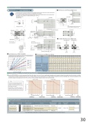
Dimensional DrawingsCAD drawings can be downloaded from the website.www.robocylinder.deDimensions with Flange (Optional)2D CAD*1 Duringhomereturn,becarefultoavoidinterferencefromperipheralobjectsbecausetheslidertravelsuntilthemechanicalend. *2 The orientation of the width across flats varies depending on the product.*3 Iftheactuatorisinstalledusingthefronthousingandflange,makesuretheactuatorwillnotreceiveanyexternalforce.(For details, refer to “Notes on Installing Rod Actuators” on P. 31.) ME: Mechanical endSE: Stroke endRod Deflection of RCP5-RA10R(The graph below shows the measurements of how much a horizontally installed rod would deflect when a load is applied to the end of the rod. The measured deflection include the deflection due to the weight of the rod.)NoteFor the specification with brake of 50-mm stroke, a flange is installed in a 90-degree angle.3 Cable Exit Directions (Optional)Stroke 50 100 150 200L 366.5 416.5 466.5 516.5 566.5 616.5 666.5 716.5 766.5 816.5 866.5 916.5 966.5 1016.5 1066.5 1116.5 A 01122334455667786.0 5.5 5.0 4.5 4.0 3.5 3.0 2.5 2.0 1.5 1.0 0.5 0.00800st 700st 600st 500st 400st 300st 200st 100st HomeB C DAllowable dynamic Load offset 0mm load at end of rod (N) Load offset 100mmAllowable static torque at end of rod (Nm) Allowable dynamic torque at end of rod (Nm) Mass (kg) Without brakeWith brake132 82 132 82 132 82 132 82 132 82 132 82 132 82 132 82 4 6 6 8 8 10 10 12 12 14 14 16 16 18 18 2050100Load at end of rod (N)119.1 99.1 100.7 85.9 31.8 27.0 10.1 9.7 14.6 15.3 16.2 16.984.7 73.8 74.9 66.3 23.4 20.7 8.5 7.5 16.0 16.7 17.6 18.365.3 58.5 59.3 53.6 18.5 16.8 6.7 6.0 17.4 18.1 19.0 19.752.8 38.7 48.8 38.7 15.3 14.1 5.5 5.0 18.8 19.5 20.4 21.129.2 22.5 29.2 22.5 13.1 12.2 4.6 4.2 20.2 20.9 21.8 22.517.7 14.2 11.6 17.7 14.2 11.6 11.4 10.7 10.1 3.9 3.6 3.3 21.6 22.3 23.0 23.2 23.9 24.6NamePositioner typePulse-train type Field network typeExternal viewModel numberPCON-CFA-86PWAI-NP- -0- PCON-CFA-86PWAI-PN- -0-FeaturesPositioner type based on PIO controlMaximum number of positioning points512 pointsInput powerDC24VPower supply capacityReference pageRefer to P. 39150200250300350Correlation Diagrams of Vertical Load and Traveling LifeDimensions and Mass by StrokeDeflection (mm)132 182 232 282 332 382 432 482 532 582 632 682 732 Allowablestaticloadatendofrod(N) 316.9268.4232.6205.1183.4165.7151.0138.6128.1119.0111.0103.9 97.7782 832 882 92.1 87.0 82.5 9.5 8.0 6.7 9.5 8.0 6.7 9.6 9.1 8.6 3.0 3.0 3.0 23.7 24.4 25.1 25.3 26.0 26.7Since the RCP5-RA10R has a greater maximum thrust than other types, its service life varies significantly depending on the payload and push force applied when the actuator is installed vertically. When selecting an appropriate type from the correlation diagram of speed and payload or correlation diagram of push force and current-limiting value, check its traveling life on the correlation diagram of payload and service life as well as on the correlation diagram of push force and service life.NoteThe rated value represents the maximum value at a traveling life of 5,000km. The greatest value is the maximum value at which the actuator can operate.Take note that, if an actuator is operated beyond its rating, its service life will drop as shown by the applicable graph on the right.Applicable ControllerRCP5 series actuators can be operated with the controller indicated below. Select the type according to your intended application.PCON-CFA-86PWAI-PLN- -0- PCON-CFA-86PWAI-PLP- -0-Refer to P. 46 * In the model numbers shown above, indicates the field network specification (DV, CC, PR, CN, PRT, EC or EP).PCON-CFA-86PWAI--0-0-Pulse-train input type Supporting major field networks— 768 points250 300 350 400 450 500 550 600 650 700750 80030
