
Page 103 - RoboCilindri, RCP4, robocilindri, sinta,
P. 103
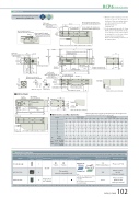
DimensionsCAD drawings can be downloaded from our website. 2DRCP6 RoboCylinder *1 When the table is returning to its homeposition, please be careful of interference from surrounding objects, as it will travel until it reaches the M.E. M.E: Mechanical endS.E: Stroke end*2 For the single guide type with 25~50mm(RCP6) and 25~125mm (RCP6S) strokes, tools cannot be used on the ø6 front mounting holes on the top surface because the motor unit interferes.Please use the mounting screw holes on the bottom surface.www.robocylinder.deGrease nipple positionwith the table fully extendedφ8.5CADC-M5 through(Bolt screw-in depth: 10 or less) φ5H7depth5.5(From mounting surface)50 B×50Grease nipple (for guide use) (used with double-guide block)Greasenipple(forguideuse) (used with single-guide block)4-M5 through 40 (Bolt screw-in depth: 10 or less) 10.5(21.2)Reference position for guide moment calculation 58 (Single-guide block)98 (Double-guide block)M3 depth 4(For ground line)5745φ5H7 depth 5S.E.HomeM.E.16 6457454-M6 depth 1244.5 (Motor side-mounted to the left) 13.5 (Motor side-mounted to the right) RCP6S-TA6R T-slot312 (Top view)Must be 100 or more168* If the length for R is negative in the table below, the length of the actuator body is shorter than the motor unit.Single Guide25 50 75 100 125 150 175 200 45 70 95 120 170 220 270 320ME R(82.1)(M3 nut)4-M6 depth 12116Applicable Controllers21 40 57 58X 6T-slot (M3 nut)3 M.E. R116(1)11758J-φ6 through φ9.5 counterbored,12160 (Double-guide block)D817.5 (1)(64.1)(except for the part in the way of the motor, same on opposite side)Reference position for guide moment calculation4.5φ5 H7 depth 5.5 (From mounting surface)2.71.5φ9.5 φ6(58)Detail view of XStandardDetail view of T-grooveM3 depth 4(For ground line)Status LEDTeaching portConnector for power supply/I/Ocableconnection168.2D250.3 (with or without brake, common )Cable exit direction (Option)Grease nipple for guide Ball screw cover (removable) Applying directly onto ball screw3 M.E.5 H7 Oblong hole depth 5StrokeA14 27.5depth 5 (From opposite side) *280 (Single-guide block)H×100Single-phase 100~230VACwill vary depending on the controller.Please refer to reference page for more information.Please see the MSEL-PC/PG catalog or manual.G-M5 depth1050 (φ5-oblonghole)(1)5 H7 Oblong hole depth 5.5 (From mounting surface)6 E×50 (M5 hole pitch) (F)StandardCJO OutsideCable exit direction (Option)CJO Outside27 (φ5-oblonghole)6 5 H7 Oblong hole depth 5.5 (Frommountingsurface)48.5157 (8)4.5 529 6.5 4565 48.516.565 60 40 30 203.3 5.829 856 50 3238.5 306.529454 3048.516.5157 (8)Must be 100 or more 12193.1 (with or without brake, common ) L Dimensions and Mass by StrokeR*RCP6 RCP6S RCP6 w/o brake-40.6 -15.6 9.4 34.4 59.4 84.4 109.4 134.4 59.4 84.4 109.4 134.4 184.4 234.4 284.4 334.4 -97.8 -72.8 -47.8 -22.8 2.2 27.2 52.2 77.2 2.2 27.2 52.2 77.2 127.2 177.2 227.2 277.2StrokeDouble GuideMass(kg) RCP6S w/obrake 2.5w/ brakew/ brake 2.5This model is network-compatible only.Note:· The type of compatible networksMSEL-PC/PG* Please select "high-output speci cation" as an option for the MCON. With the MCON, operation is possible only when the high-output speci cation is selected.- -129168.5 193.5 218.5 243.5 268.5 293.5 318.5 343.5 268.5 293.5 318.5 343.5 393.5 443.5 493.5 543.5 115 140 165 190 215 240 265 290 215 240 265 290 340 390 440 490 11223344334456784 4 6 6 8 8 10 10 8 8 10 10 12 14 16 18 117 142 167 192 217 242 267 292 217 242 267 292 342 392 442 492 2233445544556789 13 38 13 38 13 38 13 38 13 38 13 38 38 38 38 38 6 6 8 8 10 10 12 12 10 10 12 12 14 16 18 20 0000111100001122LABCDEFGHJ 44446666444466882.32.5 2.7 2.8 3.0 3.1 3.3 3.5 3.2 3.4 3.5 3.7 4.0 4.3 4.7 5.0 2.6 2.7 2.9 3.0 3.2 3.4 3.5 3.3 3.4 3.6 3.8 4.1 4.4 4.7 5.0 2.6 2.8 3.0 3.1 3.3 3.4 3.6 3.3 3.5 3.7 3.8 4.1 4.5 4.8 5.1 2.7 2.9 3.0 3.2 3.3 3.5 3.7 3.4 3.6 3.7 3.9 4.2 4.5 4.9 5.22.4The RCP6 series actuators can be operated by the controllers indicated below. Please select the type depending on your intended use. * Please refer to P.147 for more information about the built-in controller of RCP6S series.NamePCON-CB/CGBMCON-C/CGExternal viewMax. number of controlled axes1 4 4Input powerDC24VPositioner*OptionPulse train*OptionControl method Program-Network *OptionMaximum number of positioning points512(768 for network spec.)256 30000Reference pagePlease see P.132Please see the MCON catalog or manual.RCP6(S)-TA6R 102
