
Page 113 - RoboCilindri, RCP4, robocilindri, sinta,
P. 113
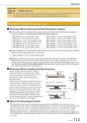
Selection Notes for RCP6(S) SeriesWarnings When Selecting the Rod Attachment Option selected for RCP6(S)-RA4R/RA6R/RA7R/RA8R/RRA4R/RRA6R/RRA7R.RRAR models, there may be some interference between the cable and installation surface forcertain strokes. Please also be careful of nearby objects when selecting the tip adapter option (FFA, NFA, KFA) for the RCP6(S)-RRA4R/RRA6R/RRA7R models, there may be some interference between the cable and work piece for certain strokes.OptionsDouble SliderOption Code W Applicable Models RCP6(S)-SADescription You can add a free-moving slider which is mounted only to the linear guide (not connected with the ball screw or the belt). The allowance of the dynamic moment and overhang load will be bigger with double slider option.*Please refer to P.131 for dynamic allowable moment and overhang load length for the double slider.• RCP6-RA4R 50mm (Standard/With a brake)• RCP6-RA6R 50mm (Standard/With a brake)• RCP6-RA7R 50~100mm (Standard/With a brake) • RCP6-RA8R 50~100mm (Standard/With a brake) • RCP6-RRA4R 60mm (Standard/With a brake)• RCP6-RRA6R 65mm (Standard/With a brake)• RCP6-RRA7R 70mm (Standard/With a brake)• RCP6S-RA4R 50~100mm (Standard/With a brake)• RCP6S-RA6R 50~100mm (Standard/With a brake)• RCP6S-RA7R 50~150mm (Standard/With a brake)• RCP6S-RA8R 50~150mm (Standard/With a brake)• RCP6S-RRA4R 60~110mm (Standard/With a brake) • RCP6S-RRA6R 65~115mm (Standard/With a brake) • RCP6S-RRA7R 70~120mm (Standard/With a brake)RRA8R when the following strokes are selected.• RCP6(S)-RRA8R 50~100mm (Standard/With a brake)Warnings When Installing the Rod ActuatorsExternal force(optional), please be careful that the actuator does not experience any external force. (External force may cause malfunctions or damaged parts)If the actuator will experience external force or is being used in conjunction with a Cartesian robot, etc., please use the mounting holes on the base of the actuator to secure it into place. Even in cases when external force will not be applied, to secure the actuator in place whenbracket mounting holes to create a support base as shown in the diagram on the right.About the Mounting PositionsExternal forceSupport baseSupport base• While installation in the side and ceiling mount positions are available, this may cause slack or misalignment in the stainless steel sheet. Continuing to use it this way could cause the stainless steel sheet to break. Please inspect it daily and adjust the sheet if any slack or misalignment is found.• When installing the motor-coupled type vertically, please set the motor on the top if possible. While installing the motor on the bottom will not cause problems in normal operation, long periodsoccasions.Options 112
