
Page 149 - RoboCilindri, RCP4, robocilindri, sinta,
P. 149
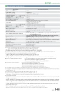
RCP6S Built-in ControllerBasic Controller Speci cation ListSpeci cationSpeci cation DescriptionNumber of controlled axes1 axisPower supply voltage24VDC±10%Control power capacity0.3A (Built-in controller only)Load current (including control-side current consumption)Motor type28P, 35P, 42P, 56P3.2A max.56SP, 60P5.7A max.Electromagnetic brake power (for actuator with brake)24VDC±10% 0.15A(Note) For releasing brake, 0.7A for 0.2 sec is required.Heat output5W (Motor type 28P, 35P, 42P, 56P) 19.2W (Motor type 56SP, 60P)Inrush current (Note 1)Motor type28P, 35P, 42P, 56P8.3A (With inrush current protection circuitry)56SP, 60P10A (With inrush current protection circuitry)Motor control methodWeak eld vector controlCompatible encoderResolution of battery-less absolute encoder: 8192 pulses/revActuator cable length20m max.Serial communication interface (SIO port)RS485: 1CH (Modbus protocol RTU/ASCII compliant) Speed: 9.6~230.4Kbps 1CH (Modbus protocol RTU)External interfaceField bus connection: DeviceNet, CC-Link, PROFIBUS-DP, EtherCAT, EtherNet/IP, PROFINET-IO. (Note) Additional gateway unit connection is required.Data setting, input methodPC compatible software, touch panel teaching pendantData retention memoryPosition data and parameters are saved in non-volatile memory. (No limit to rewrite)LED displaySV (green) / ALM (red): Servo ON / Alarm triggered and emergency stopInsulation resistanceNot less than 10MΩ at 500VDCElectric shock protection mechanismClass I basic insulationCooling methodNatural air coolingNote1: Inrush current will ow for approximately 5msec after the power is turned on (at 40°C). Inrush current value di ers depending on the impedance on the power supply line.<The Calculation of Number of Connectable Axes and Power Capacity>To calculate the number of axes connectable to one gateway unit and the current amperage of 24VDC, gure out (1) to (5) below and follow (6). (1) The Calculation of Number of Connectable Axes, and Motor Current ConsumptionCondition 1: Sum of motor current consumption connectable to one hub unit: 12.8A or lessCondition 2: Number of controlled axes connectable to corresponding 1 unit: 4 axes or less* By adjusting the number of connected axes or motor type, select the connected axes so each hub unit satis es the formulas below. Sum of motor current consumption for hub unit = Motor current consumption of 1st axis + Motor current consumption of 2nd axis (if connected) + Motor current consumption of 3rd axis (if connected)Sum of motor current consumption+ Motor current consumption of 4th axis (if connected) ≤ 12.8A····· = Motor current consumption of hub unit 1st unit+ Motor current consumption of 2nd hub unit (if connected)+ Motor current consumption of 3rd hub unit (if connected)+ Motor current consumption of 4th hub unit (if connected) ·····(2) Control Power Current Consumption: 0.3A × Number of actuator + 0.6A (gateway unit) + 0.3A × Number of hub unit ·····(3) Consumption current when excited phase detected: The maximum current value of the total motor consumption current when servos are turnedon at the same time ·····(4) Inrush Current: 8.3A (Motor type 28P, 35P, 42P, 56P) 10A (Motor type 56SP, 60P) ····· (5) Current Consumption of Brake Release: Number of actuators with brake × 0.7A ·····* When servo is on, it should be 0.5sec or less, after that retaining of released status should be 0.1A / axis. (6) Selection of Power Supply:Usually, the rated current is to be approximately 1.2 times higher than the total of Control Power++above considering approximately 20% of margin to the load current.However, although it is for a short time, current ofandwill ow, so please take this into account and select a “peak load support” speci cation or select a power supply that has su cient headroom. Avoid having all of the current fromandfrom owing at the same time by turning the servos on at di erent times from each other (Note 1).If a power supply with insu cient headroom is selected, voltage may drop instantaneously. Be careful especially when selecting a power source equipped with remote sensing.Note 1: The timing to turn the servo on can be tuned in Parameter No. 165 [Latency after Shutdown Release].(Note) Ensure motor and control power supplies reference the same potential when using multiple power supplies.RCP6S 148
