
Page 152 - RoboCilindri, RCP4, robocilindri, sinta,
P. 152
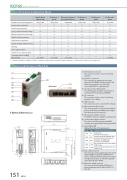
RCP6S Built-in ControllerList of Functions by Operation ModeNumber of positioning points Home return operation Positioning operationSpeed, acceleration/deceleration settings Di erent acceleration and deceleration settings Pitch Feed (Incremental) Push-motion operation Speed changes while moving PausingSimple direct value mode256 pointsPositioner 1 mode256 pointsDirect numerical control mode (Direct indication/Full mode)UnlimitedPositioner 2 mode256 pointsPositioner 3 mode256 pointsPositioner 5 mode16 pointsZone signal output Position zone signal output Current position reading —— —— — (0.01mm) (0.01mm) (0.1mm)(Resolution) (0.01mm)*indicates that direct setting is possible,indicates position data or parameter input is required, — indicates the operation is not supported.Names and Functions of Each Part(1)(2)(3) (4) (5)(6)(7) (8)External Dimensions(9)<Bottom>(10) (11)(1) (2)(3) (4)(5) (6)(7) (8)(9)(10)(11)Field network connectorThe connector used to connect to the eld network.System I/O connectorThe connector for emergency stop input, external AUTO/MANU switchover input, and brake release input in case of directly connecting RCP6S to a gateway unit.Operation mode setting switchFor switching the operation mode between automatic (AUTO) and manual (MANU).SIO connectorThe connector used to connect a teaching pendant or PC software.USBconnectorThe connector used to connect the PC software.Drive power cut-o connectorThe connector used to connect an external drive power cut-o relay to the 24VDC power supply from the motor power connector.Motor power supply connectorFor 24VDC motor power supply for a gateway unit.Control power supply connectorThe connector for the gateway unit 24VDC control power supply and the frame ground (FG).Status display LEDDisplays the status of the gateway unit.12.5352512.5Axis control connectorThe connector used to supply power and control signals (24VDC control power, 24VDC motor power, communication line, brake release signal, emergency stop status, etc.) from the gateway unit to the hub unit or RCP6S.Axis power supply connectorThe connector used to supply 24VDC motor power via gateway unit to either a RCP6S or a hub unit.151 RCP6S123 — — 6.546.5CodeLED1 LED2 LED3 LED4 LED5LEDSYS AUTO EMG T. ERR C. ERRDisplay color and operating status.System statusReady (Green) Alarm (Red)Operation mode (AUTO/MANU) status Automatic operation mode (Green) Emergency stop (EMG) status Emergency stop (EMG)(Red)Bus communication error in the controller T.ERR (Orange)Field bus network communication error C.ERR (Orange)φ5(6.5)35.4 (35mm DIN rail width)55 from the DIN rail center105115
