
Page 23 - RoboCilindri, RCP4, robocilindri, sinta,
P. 23
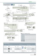
DimensionsCAD drawings can be downloaded from our website. 2D2-φ3H7 reamed, depth 6 4-M3 depth 720 (φ3H7 pitch ±0.02)RCP6 RoboCylinder*1 When the slider is returning to its home position, please be careful of40 interference from surrounding objects, 32 24 ±0.02 as it will travel until it reaches the M.E.Reference surface (B dimensions range)2-φ3 H7 depth 4Oblong hole depth 4 (From mounting surface)E-M4 through(Bolt screw-in depth: 6)H-φ3.4, φ6.5 deep counterbored, depth 3.5 (From back side)50 (25 for 50mm stroke)(54.5) 133www.robocylinder.deCAD2662610 3226111+0.010 306.11748 Top face of slider12 36103246 (2)2.53.525φ6.5 φ3.4Reference surface102539 P 40M.E: Mechanical endS.E: Stroke end*2 When xing the actuator usingcounterbored holes, please remove the side cover after removing the motor cover.RCP6S-SA4RMust be 100 or moreM3 depth 4(For ground line)35.5 (Motor side-mounted to the left) 16.5 (Motor side-mounted to the right)Motor side viewCJO OutsideCable exit direction (Option) side-mounted to the left (ML).Teaching portM3 depth 4 (For ground line)(0.5)Details of base mounting holesfor allowable moment calculationMust be 100 or more StrokeAL187.5 (same as the type with brake)76 20 3Home M.E.31Applicable Controllers1949(1)Detail view of P90 4J (φ3 hole - oblong hole) K (φ3 hole - φ3 hole)(94.3)165113M.E.123 S.E.32 4-M4 depth 8(From mounting surface)(R1.5)207.3 (same as the type with brake)3216Status LEDMotor side viewCJO Outside17 Cable exit direction (Option)side-mounted to the left (ML).26 (Same as motor side-mounted to the right)Stroke LABCDEFGHJK50 100 189 239 158 208 134 184 50 50150 200 250 300 289 339 389 439 258 308 358 408 234 284 334 384 100 50 100 50350 400 450 500 489 539 589 639 458 508 558 608 434 484 534 584 100 50 100 5050C 8G×100P 12 D×100P (50 for 50mm stroke) 20BFThe RCP6 series actuators can be operated by the controllers indicated below. Please select the type depending on your intended use. * Please refer to P.147 for more information about the built-in controller of RCP6S series.NamePCON-CB/CGBMCON-C/CGExternal viewMax. number of controlled axes1 4 4Input powerDC24VPositioner*OptionPulse train*OptionControl method Program-Network *OptionMaximum number of positioning points512(768 for network spec.)256 30000Reference pagePlease see P.132Please see the MCON catalog or manual.Single-phase 100~230VACwill vary depending on the controller.Please refer to reference page for more information.Please see the MSEL-PC/PG catalog or manual.This model is network-compatible only.Note:· The type of compatible networksMSEL-PC/PG* Please select "high-output speci cation" as an option for the MCON. With the MCON, operation is possible only when the high-output speci cation is selected.- -Mass (kg)RCP6 RCP6Sw/o brake w/ brake w/o brake w/ brake50 100 1.3 1.4 1.4 1.5 1.4 1.5 1.5 1.6100 200 1.5 1.6 1.5 1.6 1.6 1.7 1.7 1.8200 300 1.7 1.7 1.7 1.8 1.8 1.9 1.8 1.9300 400 1.8 1.9 1.9 2.0 2.0 2.0 2.0 2.1400 500 2.0 2.1 2.1 2.2 2.1 2.2 2.2 2.34-M4 depth 8Dimensions and Mass by Stroke-1122334456 6 6 8 8 10 10 12 12 14 50 100 50 100 50 100 50 100 50 100 0011223344 8 8 10 10 12 12 14 14 16 16 35 85 85 185 185 285 285 385 385 485RCP6(S)-SA4R 22
