
Page 31 - RoboCilindri, RCP4, robocilindri, sinta,
P. 31
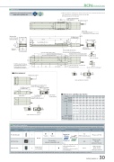
DimensionsCAD drawings can be downloaded from our website. www.robocylinder.de2D CAD*1 When the slider is returning to its home position, please be careful of interference from surrounding objects, as it will travel until it reaches the M.E.M.E: Mechanical end S.E: Stroke endposition for allowable 98 (Slider width) moment calculation 9274AReference surface(71) 1 98100 (Base width)Grease nipple (both sides)100±0.02 (n/a for 50&100mm strokes)R-oblong hole From base mounting surface depth 55.51.3P-φ5H7 reamed From base mounting surface depth 5R-oblong hole From base mounting surface depth 5RCP6S-WSA10CK-φ5.5 through -φ11 counterbored (From opposite side)Side T-slot detailsφ5.5Details of base mounting partCJT TopCJB Bottom35 M.E.StrokeS.E. T-slot : M3 (both sides)160 48 Home M.E.97 (Motor unit width)3535 G3535P-φ5H7 reamed From base mounting surface depth 5Must be 100 or moreQ (n/a for 50&100mm strokes)Q (n/a for 50&100mm strokes)N±0.02 (n/a for 50&100mm strokes)6100 (H) J×100 pitch380 502-φ5H7 reamed, depth 5L4 4 24.15.52-M3 depth 6 (For ground line)4-M5 depth 14Must be 100 or moreMotor unit* It is possible to mountthe motor unit at 180 degree rotated.129 (Without brake) 159 (With brake)(0.3)25CJL LeftCJR RightRCP6 RoboCylinder3241 521.53225.53.35.8 21.584+0.012 5017647 3226.5 (0.5)1 41 583(φ5H7 pitch: ±0.02)Applicable Controllers159 (Without brake) 174 (With brake)* It is possible to mount the motor unit at 180 degree rotated.97 (Motor unit width)Status LED2-M3 depth 6 (For ground line) Dimensions and Mass by Stroke25AGHJ 0011223344 K 4 4 8 8 10 10 12 12 14 14 N - - 100 100 100 100 100 100 100 100 P 1122222222 Q - - 206 256 306 356 406 456 506 556 R 00111111115.5 23.1Teaching portConnector for power supply/I/O cable connectionCJT TopCJB Bottom5.5Cable exit direction (Option)RCP6 w/o brake w/ brake RCP6S w/obrake w/ brake2.9 3.1 3.1 3.3 3.0 3.2 3.1 3.43.4 3.6 3.6 3.8 3.5 3.7 3.6 3.93.8 4.1 4.0 4.3 3.9 4.2 4.1 4.34.3 4.6 4.5 4.8 4.4 4.7 4.6 4.84.8 5.0 5.0 5.2 4.9 5.1 5.1 5.3CJR RightThe RCP6 series actuators can be operated by the controllers indicated below. Please select the type depending on your intended use. * Please refer to P.147 for more information about the built-in controller of RCP6S series.NamePCON-CB/CGBMCON-C/CGExternal viewMax. number of controlled axes1 4 4Input powerDC24VPositioner*OptionPulse train*OptionControl method Program-Network *OptionMaximum number of positioning points512(768 for network spec.)256 30000Reference pagePlease see P.132Please see the MCON catalog or manual.Single-phase 100~230VACwill vary depending on the controller.Please refer to reference page for more information.Please see the MSEL-PC/PG catalog or manual.This model is network-compatible only.Note:· The type of compatible networksMSEL-PC/PG* Please select "high-output speci cation" as an option for the MCON. With the MCON, operation is possible only when the high-output speci cation is selected.- -LMass (kg)StrokeRCP6 w/o brakew/ brake RCP6S w/obrakew/ brake50 100 422 472 452 502 452 502 467 517 293 343 - - 156 206150 200 250 300 350 522 572 622 672 722 552 602 652 702 752 552 602 652 702 752 567 617 667 717 767 393 443 493 543 593 100 100 100 100 100 56 106 56 106 56400 450 500 772 822 872 802 852 902 802 852 902 817 867 917 643 693 743 100 100 100 106 56 106Cable exit direction (Option)RCP6(S)-WSA10C 30
