
Page 41 - RoboCilindri, RCP4, robocilindri, sinta,
P. 41
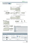
DimensionsCAD drawings can be downloaded from our website. www.robocylinder.de2D CADRCP6 RoboCylinder *1 When the slider is returning to its home position, please be careful of interference fromMust be 100 or more273.5 (Without brake, with brake) Status LED19.5position for allowable moment calculationReference surface117 (Slider width) 11191118120 (Base width)P-φ6H7 reamed From base mounting surface depth 6R-oblong hole From base mounting surface depth 6Must be 100 or moreM3 depth 6(For ground line)19.5RCP6S-WSA12R3 1.3Side T-slot details1(89)(1)(37.3) 65T-slot : M3 (both sides)30(5.9)51.5 51.5 103(5.9) Teaching port M3depth6(Forgroundline) Connectorforpowersupply/I/OcableconnectionApplicable ControllersStroke LAGH50 100 150 200 250 300 350 400 450 500 550 600 650 700 750 800 308.5 358.5 408.5 458.5 508.5 558.5 608.5 658.5 708.5 758.5 808.5 858.5 908.5 958.5 1008.5 1058.5 289.5 339.5 389.5 439.5 489.5 539.5 589.5 639.5 689.5 739.5 789.5 839.5 889.5 939.5 989.5 1039.5- - 100 100 100 100 100 100 100 100 100 100 100 100 100 100 148.5 198.5 48.5 98.5 48.5 98.5 48.5 98.5 48.5 98.5 48.5 98.5 48.5 98.5 48.5 98.50011223344556677 4 4 8 8 101012121414161618182020 - - 100 100 100 100 100 100 100 100 100 100 100 100 100 100 1122222222222222- - 198.5 248.5 298.5 348.5 398.5 448.5 498.5 548.5 598.5 648.5 698.5 748.5 798.5 848.5 0011111111111111NamePCON-CB/CGBMCON-C/CGExternal viewMax. number of controlled axes1 4 4Input powerDC24VPositioner*OptionPulse train*OptionControl method Program-Network *OptionMaximum number of positioning points512(768 for network spec.)256 30000Reference pagePlease see P.132Please see the MCON catalog or manual.186Q (n/a for 50&100mm strokes)Q (n/a for 50&100mm strokes) N±0.02 (n/a for 50&100mm strokes)100±0.02 (n/a for 50&100mm strokes)R-oblong hole From base mounting surface depth 641.5 Stroke5 705M.E.S.E.30 G (H)6-M6 depth 1051.5 51.5 1037100 J×100 pitch3030CJO OutsideP-φ6H7 reamed From base mounting surface depth 6K-φ6.6 through -φ12.5 counterbored (From opposite side)Cable exit direction (Option)the motor side-mounted to the left (ML).K N P Q RSingle-phase 100~230VACwill vary depending on the controller.Please refer to reference page for more information.Please see the MSEL-PC/PG catalog or manual.CJOOutside JThis model is network-compatible only.Note:· The type of compatible networksMSEL-PC/PG* Please select "high-output speci cation" as an option for the MCON. With the MCON, operation is possible only when the high-output speci cation is selected.- -MassThe RCP6 series actuators can be operated by the controllers indicated below. Please select the type depending on your intended use. * Please refer to P.147 for more information about the built-in controller of RCP6S series.surrounding objects, as it will travel until it reaches the M.E. M.E: Mechanical end S.E: Stroke end2-φ6H7 reamed, depth 6 4-M6 depth 18LA 19140 58 50 Home M.E.213.5 (Without brake, with brake)265.5 411861 26 50 526193.3 5.8301036+0.012 02656637 325.5 41(0.5)101 (φ6H7 pitch: ±0.02)Cable exit direction (Option)φ6.6Details of base mounting partDimensions and Mass by StrokeRCP6 w/obrake 4.1 4.4 4.7 5.1 5.4 5.7 6.1 6.4 6.7 7.1 7.4 7.7 8.1 8.4 8.7 9.1 w/brake 4.1 4.5 4.8 5.1 5.5 5.8 6.1 6.5 6.8 7.1 7.5 7.8 8.1 8.5 8.8 9.1 (kg) RCP6S w/obrake 4.2 4.5 4.9 5.2 5.5 5.9 6.2 6.5 6.9 7.2 7.5 7.9 8.2 8.5 8.9 9.2 w/brake 4.3 4.6 4.9 5.3 5.6 5.9 6.3 6.6 6.9 7.3 7.6 7.9 8.3 8.6 8.9 9.36-M6 depth 10RCP6(S)-WSA12R 40
