
Page 69 - RoboCilindri, RCP4, robocilindri, sinta,
P. 69
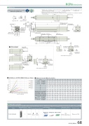
DimensionsCAD drawings can be downloaded from our website. 2DRCP6 RoboCylinder*1 When the rod is returning to its home position, please be careful of interference from surrounding objects, as it will travel until it reaches the M.E. M.E: Mechanical end S.E: Stroke end*2 The direction of width across ats varies depending on the product.*3 When xing the actuator using a front bracket or ange, please make sure that there is no external force applied3.0 2.5 2.0 1.5 1.0 0.5 0.0 0Stroke50 100 150 200 250 300 350 400 450 500 550 600 650 700539.5 589.5 639.5 689.5 739.5 789.5 839.5 889.5 939.5 989.5 1039.5 1089.5www.robocylinder.deCAD9Detail view of P 4-M8 depth 1630 12M20×1.5 Supplied hex nut75.5Grease nipple LMust be 100 or more2-M3 depth 6 (For ground line)CJT Top32CJB BottomReference surface (B dimensions range)40 26RCP6S-RRA8C185 (Without brake) 215 (With brake)Status LEDMust be 100 or more2-M3 depth 6 (For ground line)85 40Unavailable when CJL is selected.CJL LeftCable exit direction (Option)6735 65 83 85M20×1.5M.E.The orientation ofis indeterminable (*2)4 S.E.4Home M.E. 5147 (Without brake) 177 (With brake)85 50Connector for power supply/I/O cable connection Teaching port2-M3 depth 6 (For ground line)CJR RightUnavailable when CJR is selected.10 20 30 40 50 60 70 80 90 100110120130140150 Load on rod tip (N)222 186 9.5 7.8 7.4 6.3 22.3 18.7 7.2 6.2 6.6 7.1 7.2 7.7 7.0 7.4 7.5 8.0159 139 6.6 5.7 5.5 4.9 16.1 14.1 5.4 4.8 7.6 8.0 8.2 8.6 7.9 8.4 8.5 9.0124 111 5.0 4.5 4.4 4.0 12.6 11.3 4.3 3.9 8.5 9.0 9.1 9.6 8.8 9.3 9.4 9.9101 92.1 4.0 3.6 3.6 3.3 10.3 9.4 3.5 3.2 9.5 9.9 10.1 10.5 9.8 10.3 10.4 10.884.7 78.4 3.3 3.0 3.0 2.8 8.7 8.1 3.0 2.7 10.4 10.9 11.0 11.5 10.7 11.2 11.3 11.872.8 68 2.8 2.6 2.6 2.4 7.6 7.1 2.5 2.4 11.4 11.8 11.9 12.4 11.7 12.1 12.3 12.763.7 59.8 2.4 2.2 2.2 2.1 6.7 6.3 2.2 2.0 12.3 12.8 12.9 13.4 12.6 13.1 13.2 13.7Applicable ControllersStroke 7824CJT Top 29.4CJB Bottom Rod De ection of RCP6(S)-RRA8C (Reference Values) Dimensions and Mass by StrokeHome 100st 200st 300st 400st 500st 600st 700stw/o brake w/ brake w/o brake w/ brakeABCDEJAllowable static load on rod tip (N)Allowable dynamic Load o set 0mm load on rod tip (kg) Load o set 100mm Allowable static torque on rod tip (N•m) Allowable dynamic torque on rod tip (N•m)439.5 489.5 469.5 519.5 477.5 527.5 507.5 557.53020J (φ8 hole-oblong hole) BD×100P5047.5PCUnavailable when CJL is selected.CJL LeftE-M8through(Bolt screw-in depth: 12)to the main body.AOblongholedepth6.5 φ8H7depth6.5 (Frommountingsurface) (Frommountingsurface)(R4)26 1837 90.5 18 17.120325.6φ65 h7 φ40 (Rod outer diameter)50133 18.290.586 (4.5)6743.5 80+0.010(34.6)Cable exit direction (Option)RCP6 LRCP6S769.5 819.5777.5 827.5807.5 857.5292.5 342.5 392.5 442.5 492.5 542.5 592.5 642.5 692.5 742.5 792.5 842.5 892.5 942.5 215 265 315 365 415 465 515 565 615 665 715 765 815 865 115 65 115 65 115 65 115 65 115 65 115 65 115 65 011223344556674 6 6 8 8 10 10 12 12 14 14 16 16 18 115 165 215 265 315 365 415 465 515 565 615 665 715 765RCP6 (kg) RCP6Sw/o brake w/ brake w/o brake w/ brakeMassThe RCP6 series actuators can be operated by the controllers indicated below. Please select the type depending on your intended use. * Please refer to P.147 for more information about the built-in controller of RCP6S series.ZU_RCP6-RRA8C External Max. number of Name view controlled axesPCON-CFB/CGFB 1Input powerDC24VControl methodMaximum numberof positioning points Reference page512 Please see P.132 (768 for network spec.)Positioner Pulse train Program - *Option *OptionNetwork *Option569.5 619.5 577.5 627.5 607.5 657.5669.5 719.5 677.5 727.5 707.5 757.5869.5 919.5 969.5 1019.5 1069.5 1119.5 877.5 927.5 977.5 1027.5 1077.5 1127.5 907.5 957.5 1007.5 1057.5 1107.5 1157.5252-M3 depth 6 (For ground line)CJR RightUnavailable when CJR is selected.RCP6(S)-RRA8C 68
