
Page 73 - RoboCilindri, RCP4, robocilindri, sinta,
P. 73
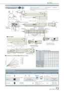
DimensionsCAD drawings can be downloaded from our website. 2Dwww.robocylinder.de 17 6RCP6 RoboCylinder*1 When the rod is returning to its home position, please be careful of interference from surrounding objects, as it will travel until it reaches the M.E. M.E: Mechanical end S.E: Stroke end*2 The direction of width across ats varies depending on the product.*3 When xing the actuator using a front bracket or ange, please make sure that there is no external force applied3310.5 4533117332810.54533405 3361φ30 h7 φ25 (Rod outer diameter)54 (7) +0.010(19.6)4.94.5 5.58.5Detail view of PReference surface (B dimensions range)(0.5)Details of base mounting holesM10×1.25 Supplied hex nutφ8 φ4.55RCP6S-RRA6RMust be 100 or moreTeaching port10 18 B 12102030Load on rod tip (N)6070 80Mass (kg)RCP6 RCP6Sw/o brake w/ brake w/o brake w/ brake3.9 3.3 2.8 2.5 3.0 2.7 2.4 2.1 10.0 8.7 7.6 6.8 2.9 2.6 2.3 2.0 2.9 3.1 3.3 3.5 2.9 3.2 3.4 3.6 3.0 3.2 3.4 3.7 3.1 3.3 3.5 3.72.2 2.0 1.9 1.7 6.2 5.6 1.8 1.6 3.8 4.0 3.8 4.1 3.9 4.1 4.0 4.2Reference surfaceApplicable Controllers17.5 38.5 57 5848.5 (Motor side-mounted to the left)(82.1)250.3 (same as the type with brake) 168.2212M3 depth 4 (For ground line)Status LEDStroke LABH 4 4 6 6 8 8 10 10 J 0 85 85 185 185 285 285 385 K 0 100 100 200 200 300 300 400M 23333333 N 01111111(1)21.2 11758M.E.41.5 3 3227.54-M6 depth 12, 90° equipartition193.1 (same as the type with brake) (64.1) 12945Rod De ection of RCP6(S)-RRA6R (Reference Values) 2.5172 222 272 322 372 422 472 522 D 01122334 E 4 6 6 8 8 10 10 12 G 112233442.0 1.5 1.0 0.5 0.00Home 65st 115st 165st 215st 265st 315st 365st 415stAllowable static load on rod tip (N) Allowable dynamic Load o set 0mm load on rod tip (kg) Load o set 100mm Allowable static torque on rod tip (N•m) Allowable dynamic torque on rod tip (N•m)144 117 5.9 4.7 4.0 3.5 14.5 11.8 3.8 3.3 2.4 2.6 2.5 2.7 2.6 2.8 2.6 2.899 85.4 75 66.7 59.9 54.34050CAD Stroketo the main body. AMust be 100 or moreLS.E. Home M.E. M10×1.2522 12M-φ4 H7 depth 5.5 (From mounting surface)Grease nipple32.5(R2)P.C.D.4045°PN-oblong hole depth 5.5 (From mounting surface)H-φ4.5, φ8 counterbored, depth 4.5 (From back side)E-M5 through(Bolt screw-in depth: 10)CJO Outside4548.5 (Motor side-mounted to the left) 17.5 (Motor side-mounted to the right)Dimensions and Mass by StrokeM3 depth 4(For ground line) 17.5 (Motor side-mounted to the right)G×100P J (φ4 hole - oblong hole)K (φ4 hole - φ4 hole)D×100P 6530CJO Outside15.8 Cable exit direction (Option)side-mounted to the left (ML). 4-M6 depth 1214.6 Cable exit direction (Option)side-mounted to the left (ML).The RCP6 series actuators can be operated by the controllers indicated below. Please select the type depending on your intended use. * Please refer to P.147 for more information about the built-in controller of RCP6S series.NamePCON-CB/CGBMCON-C/CGExternal viewMax. number of controlled axes1 4 4Input powerDC24VPositioner*OptionPulse train*OptionControl method Program-Network *OptionMaximum number of positioning points512(768 for network spec.)256 30000Reference pagePlease see P.132Please see the MCON catalog or manual.Single-phase 100~230VACwill vary depending on the controller.Please refer to reference page for more information.Please see the MSEL-PC/PG catalog or manual.This model is network-compatible only.Note:· The type of compatible networksMSEL-PC/PG* Please select "high-output speci cation" as an option for the MCON. With the MCON, operation is possible only when the high-output speci cation is selected.- -65 115 165 215229.5 279.5 329.5 379.5 429.5 479.5 529.5 579.5202 252 302 352 402 452 502 552265 315365 415RCP6(S)-RRA6R 724-M6 depth 12
