
Page 92 - RoboCilindri, RCP4, robocilindri, sinta,
P. 92
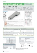
RCP6 RoboCylinder RCP6(S)-WRA16R24VPulse Motor* Body width does not include the width of the side- mounted motor. Model Speci cation ItemsSeriesWRA16R WAType Encoder Type60PMotor Type60P: Pulse Motor60SizeLead20: 20mm 10: 10mm 5: 5mmStroke50: 50mm800: 800mm (50mm increments)Applicable Controller/I/O TypeSide-mounted MotorCable Length OptionsRCP6: Separate Controller RCP6S: Built-in ControllerWA: Battery-less Absolute[RCP6]P4: PCON-N : NoneP : 1mS : 3mM : 5mX : Speci ed Length when ordering the side- R : Robot Cable mounted motor type.* RCP6 does not include a controller. RCP6S includes a built-in controller.Radial Load OKSE: SIO Typespecify either ML or MRHorizontal Side*Depending on the model, there may be some limitations to using the vertical, side, and ceiling mount positions. Please contact IAI for more information regarding mounting positions.Selection Notes120 100 80 60 40 20 00Lead 5Lead 5 assumes operation at 0.1G, the other leads assume operation at 0.2G.CeilingBattery- Motor less Unit Absolute CoupledBody WidthPayload (kg) Payload (kg)Vertical~CFB/CGFB [RCP6S]Please refer to the options table below. *Please make sure to Correlation Diagrams of Speed and Payload PCON connected.RCP6(S)-WRA16R Horizontal mount58Lead 10Lead 20160* mmIONPTActuator Speci cationsLead and PayloadModel Number(**) The payload assumes that there is an external guide. Stroke and Max. SpeedSpeed (mm/s)550 600 650 (mm) (mm) (mm)(Unit: mm/s)700 750 800 (mm) (mm) (mm)The gure above is the motor side-mounted to the left (ML).(1) The maximum acceleration/deceleration is 0.1G for lead 5 and 0.2G for lead 10/20.(2) The actuator speci cation displays the payload's maximum value, but it will vary depending on the acceleration and speed. Please refer to the "Selection Guidelines" (RCP6 Tables of Payload by Speed/Acceleration) on P.115 for more details.(3) The radial cylinder is equipped with a built-in guide. Please refer to the graphs shown in P.127 and after for the allowable loadmass.(4) When performing push-motion operation, please con rm the push force of each model by checking the "Correlation d i a g r a m o f p u s h f o r c e a n d c u r r e n t l i m i t " o n P. 1 1 3 .(5)ForRCP6S(built-incontrollertype),pleaselimitthedutycycleto70%orless..(6)Theservicelifeofanactuatorwithlead5variesdependingonthepayloadwhenusingvertically.PleaserefertoP.114for more information.RCP6(S)-WRA16R Vertical mount 80RCP6(S)-WRA16R-WA-60P-20---- 20420400 340 295 260 225 200 180RCP6(S)-WRA16R-WA-60P-10---- 10 60 34.5RCP6(S)-WRA16R-WA-60P-5---- 5 100 63 Legend: Stroke Applicable controller/I/O type Cable length Options10230 <180> <180>195 165 145 125 110 100 90Cable LengthCable Type StandardSpeci ed LengthCable Code P (1m)S (3m)M (5m)X06 (6m) ~ X10 (10m) X11 (11m) ~ X15 (15m) X16 (16m) ~ X20 (20m) R01 (1m) ~ R03 (3m) R04 (4m) ~ R05 (5m) R06 (6m) ~ R10 (10m) R11 (11m) ~ R15 (15m) R16 (16m) ~ R20 (20m)Actuator Speci cationsItem Drive systemPositioning repeatabilityLost motionRodRod non-rotation precision (*) Allowable load and torque on rod tip Rod tip o set/overhang distance Ambient operating temp. & humidityDescription Ball screw ø16mm, rolled C10±0.01mm0.1mm or lessø45mm Stainless steel0 deg.See P. 129dx: 150mm or less / dz: 100mm or less 0~40°C, 85% RH or less (Non-condensing)Robot Cable* Refer to P.144 for more information regarding the maintenance cables.(*) Rod's angular displacement in rotational direction with no load applied to the rod.OptionsName BrakeCable exit direction (Outside) FlangeMotor side-mounted to the left Motor side-mounted to the right Non-motor end speci cation T-slot nut bar (Left) (*)T-slot nut bar (Right) (*)Option CodeB CJO F L ML MR NM NTBL N T B RReference Page See P.105 See P.105 See P.106 See P.109 See P.109 See P.110 See P.110 See P.110O set distance at end of rod (dx: 150mm or less)Load at end of rodOverhang distance at end of rod (dz: 100mm or less)Load at end of rod91 RCP6(S)-WRA16RLead (mm)Max. PayloadHorizontal (kg) (**) Vertical 30 -Stroke (mm)50~800 (The incrementof stroke is 50mm)Lead 50 100 (mm) (mm) (mm)20 280 4052405 120 115 95 80 70 60 55 50 45(*) When selecting T-slot nut bar option with a side-mounted motor model, please choose NTBR when the motor is side-mounted to the left, and NTBL when the motor is side-mounted to the right.<100><100>70 60 50 40 30 20Lead 5Lead 5 assumes operation at 0.1G, the other leads assume operation at 0.2G.150~400 450 500 (mm) (mm) (mm)Lead 10 2.51810.550 100 150 200 250 300 350 400 450 500 Speed (mm/s)10 200 50 100 150 200 250 300 350 400 450 500Values in brackets < > are for vertical use.
