
Page 94 - RoboCilindri, RCP4, robocilindri, sinta,
P. 94
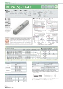
RCP6 RoboCylinder RCP6(S)-TA4CTable TypeApplicable Controller/I/O Type[RCP6] P3: PCONMCONMSEL [RCP6S]SE: SIO TypeMotor Unit CoupledCable LengthBody Width24VPulse Motor Model Speci cation ItemsTA4C WASeries Type Encoder Type35PMotor Type35P: Pulse Motor35SizeLead16: 16mm 10: 10mm 5: 5mm 2.5:2.5mmStroke25: 25mm 240: 240mmOptionsPlease refer to the options table below.RCP6: Separate Controller RCP6S: Built-in ControllerWA: Battery-less AbsoluteN : NoneP : 1mS:3mM:5mX : Speci ed Length R : Robot Cable* RCP6 does not include a controller. RCP6S includes a built-in controller.HorizontalSideCeiling*Depending on the model, there may be some limitations to using the vertical, side, and ceiling mount positions. Please contact IAI for more information regarding mounting positions.Correlation Diagrams of Speed and Payload High-output enabled (*) with PCON/MCON/MSEL connected.RCP6(S)-TA4C Horizontal mount, single guide10 9 8 7 6 5 4 3 2 1 010 9Lead 2.5Lead 5Lead 160 100 200 300 400 500 600 700 800 900 1000 Speed (mm/s)RCP6(S)-TA4C Horizontal mount, double guide 121210 Lead 2.5 8Straight Motor40 mmDoubleGuide Single GuidePayload (kg) Payload (kg)Payload (kg) Payload (kg)Vertical~RCP6(S)-TA4C Vertical mount, single guideLead 16/10 assumes operation at 0.5G, the other leads assume operation at 0.3G.5 Lead 5 Lead 10 4Lead 16 assumesoperation at 1.0G,lead 10 assumesoperation at 0.7G,the other leads assume 6 operation at 0.3G.2.53 2.52 Lead 1610 Lead 100 100 200 300 400 500 600 700 800 900 1000Speed (mm/s) RCP6(S)-TA4C Vertical mount, double guide8 Lead 2.5 7IONPTSelection Notes200 100 200 300 400 500 600 700 800(1) The maximum acceleration/deceleration is 1G for horizontal, and 0.5G for vertical use.(2) The actuator speci cation displays the payload's maximum value, but it will vary depending on the acceleration and speed. Please refer to the "Selection Guidelines" (RCP6 Tables of Payload by Speed/Acceleration) on P.115 for more details.(3) When performing push-motion operation, please con rm the push force of each model by checking the "Correlation diagram of push force and current limit" on P.113.(4) High-rigidity (double-block guide) speci cation can be selected as an option.6Actuator Speci cations (*)Lead and PayloadModel Number(*) For high output setting to OFF refer to the RCP6 manual.(*) For values of disabled high output controller setting refer to the RCP6 manual.RCP6(S)-TA4C-WA-35P-16---- 16 RCP6(S)-TA4C-WA-35P-10---- 10 RCP6(S)-TA4C-WA-35P-5---- 5 RCP6(S)-TA4C-WA-35P-2.5---- 2.5 RCP6(S)-TA4C-WA-35P-10---- 10 RCP6(S)-TA4C-WA-35P-5---- 5 RCP6(S)-TA4C-WA-35P-2.5---- 2.5High-output Enabled 3 High-output Enabled 4 High-output Enabled 5 High-output Enabled 5 High-output Enabled 8 High-output Enabled 10 High-output Enabled 10Legend: Stroke Applicable controller/I/O type Cable length Options Cable LengthValues in brackets <> are for vertical use.Cable Type StandardSpeci ed LengthCable Code P (1m)S (3m)M (5m)X06 (6m) ~ X10 (10m) X11 (11m) ~ X15 (15m) X16 (16m) ~ X20 (20m) R01 (1m) ~ R03 (3m) R04 (4m) ~ R05 (5m) R06 (6m) ~ R10 (10m) R11 (11m) ~ R15 (15m) R16 (16m) ~ R20 (20m)Item Drive systemPositioning repeatability Lost motionBaseStatic allowable momentDynamic allowable moment (*)Single guide Double guide Single guide Double guideDescription Ball screw ø8mm, rolled C10±0.01mm0.1mm or lessMaterial: Aluminum with white alumite treatment Ma: 13N•m, Mb: 18.6N•m, Mc: 25.3N•mMa: 76.8N•m, Mb: 110N•m, Mc: 50.5N•mMa: 4.98N•m, Mb: 7.11N•m, Mc: 9.68N•mMa: 23.9N•m, Mb: 34.1N•m, Mc: 15.7N•m0~40°C, 85% RH or less (Non-condensing)Robot Cable* Refer to P.144 for more information regarding the maintenance cables.Ambient operating temperature & humidityOptionsName BrakeCable exit direction (Top)Cable exit direction (Right)Cable exit direction (Left)Cable exit direction (Bottom) High-rigidity (Double-block guide) Non-motor end speci cationOption CodeB CJT CJR CJL CJB DB NMReference Page See P.105 See P.105 See P.105 See P.105 See P.105 See P.105 See P.110(*) Assumes a standard rated life of 5000km. The service life will vary depending on operation and installation conditions.Allowable load moment directionsMa Mb McPlease refer to the RoboCylinder General Catalog for more information regarding the directions of the allowable moment and overhang load length.Please refer to the RCP6 manual regarding the displacement of the table.93 RCP6(S)-TA4CLead (mm)Connected ControllerLead ConnectedDouble GuideMax. PayloadStroke (mm)25~150 (The incrementof stroke is 25mm)40/65/ 90~240 (The increment of stroke is 50mm)(Unit: mm/s)Single Guide25~150 40~190 240980 - <700>785 785 680 <700> <700>390 390 340 195 195 170Horizontal (kg)Vertical (kg)1 2.5 5 10 2.5 5 10(mm) 1610 5 2.5ControllerHigh-output EnabledHigh-output EnabledHigh-output EnabledHigh-output Enabled10 Lead 5Lead 10 assumes operation at 0.7G, the other leads assume operation at 0.3G.Lead 10 assumes operation at 0.5G, the other leads assume operation at 0.3G.Lead 586 Lead 2.5 4200 100 200 300 400 500 600 700 800Speed (mm/s)7 7 7Lead 10 4Actuator Speci cationsStroke and Max. Speed5Speed (mm/s)Lead 10 0.5
