
Page 95 - RoboCilindri, RCP4, robocilindri, sinta,
P. 95
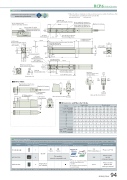
DimensionsCAD drawings can be downloaded from our website. www.robocylinder.deGrease nipple positionwith the table fully extended2D CADRCP6 RoboCylinder *1 When the table is returning to its home position, please be careful of interference fromφ8.5Grease nipple for guideBall screw cover (removable) Applying directly onto ball screw4-M4 through 3 (Bolt screw-in depth: 8 or less)StrokeS.E. Home10 M.E.312430 φ4 H7 depth 5 7.59 30 39 40M.E.44 (Single-guide block) 74 (Double-guide block)M.E. 10.565 (Single-guide block) 130 (Double-guide block)2-M3 depth 6 (For ground line)Reference position for guide moment calculationφ8 φ5Detail view of X RCP6S-TA4CPay attention to interferencewith mounted parts.(30)31 (4.5) 193 (With brake)Cable exit direction (Option)5 14.5J-φ5 throughφ8 counterbored, 13.5depth 4 (From opposite side) φ4 H7 depth 4 (From mounting surface)D H×1004 H7 Oblong hole depth 4.5 (From mounting surface)E×50 (M4 hole pitch)(39)5(F)(For ground line) 25167 (Without brake)Cable exit direction (Option)Applicable ControllersX 4 H7 oblong hole depth 53 510G-M4 through(Bolt screw-in depth: 7.5 or less)50 (φ4-oblong hole)M3 depth 5 CJT (Same on opposite side) Top22φ4 H7 depth 4.5 (Frommountingsurface)B×50Must be 100 or moreMust be 100 or moreTeaching port Status LED2-M3 depth 6 (For ground line)CJL LeftCJR Right325054 H7 Oblong hole depth 4.5 (From mounting surface)C-M4 through(Bolt screw-in depth: 6 or less)Grease nipple (for guide use) (used with double-guide block)Grease nipple (for guide use) (used with single-guide block)AReference position for guide moment calculation39 3039.9CJR Right20CJT TopCJB BottomCJL Left32CJB Bottomsurrounding objects, as it will travel until it reaches the M.E. M.E: Mechanical end S.E: Stroke end0.51970.538 25 1547.542 1216.530 4535.53.5454 42120.549.5 4.554 29 1525 8 2023.5 20L124 (Without brake) 155 (With brake)Dimensions and Mass by StrokeLMass (kg)A B C D E F G H J1122332334564 4 6 6 8 8 6 8 8 10 12 14 95.5 120.5 145.5 170.5 195.5 220.5 170.5 195.5 220.5 270.5 320.5 370.5 12233433456735.5 10.5 35.5 10.5 35.5 10.5 10.5 35.5 10.5 10.5 10.5 10.5 4 6 6 8 8 10 8 8 10 12 14 16 000011000112 444466444668The RCP6 series actuators can be operated by the controllers indicated below. Please select the type depending on your intended use. * Please refer to P.147 for more information about the built-in controller of RCP6S series.NamePCON-CB/CGBMCON-C/CGExternal viewMax. number of controlled axes1 4 4Input powerDC24VPositioner*OptionPulse train*OptionControl method Program-Network *OptionMaximum number of positioning points512(768 for network spec.)256 30000Reference pagePlease see P.132Please see the MCON catalog or manual.Single-phase 100~230VACwill vary depending on the controller.Please refer to reference page for more information.Please see the MSEL-PC/PG catalog or manual.This model is network-compatible only.Note:· The type of compatible networksMSEL-PC/PG* Please select "high-output speci cation" as an option for the MCON. With the MCON, operation is possible only when the high-output speci cation is selected.- -StrokeRCP6 w/o brake w/ brake RCP6S w/o brake w/ brakeSingle GuideDouble GuideRCP6w/o brake 1.2 1.3 1.4 1.51.6 1.6 1.7 1.8 1.7 1.8 1.9 2.01.5 1.6 1.7 1.8 1.7 1.8 1.9 2.01.7 1.9 1.9 2.0 1.9 2.1 2.1 2.22.1 2.2 2.2 2.4 2.3 2.4 2.4 2.6w/ brake RCP6S w/o brake w/ brake1.4 1.4 1.4 1.5 1.5 1.61.5 1.6 1.6 1.7 1.7 1.825 50 75 257 282 307 288 313 338 300 325 350 326 351 376 92 117 142100 332 363 375 401 167125 150 40 357 382 332 388 413 363 400 425 375 426 451 401 192 217 16765357 382 388 413 400 425 426 451 192 217140 190 240 432 482 532 463 513 563 475 525 575 501 551 601 267 317 36790RCP6(S)-TA4C 94
