
Page 33 - RoboCilindri, Controller, robocilindri, sinta,
P. 33
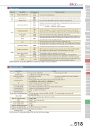
ClassificationSIOPosition movementSpecificationTypePositioning commandBackup memoryElectromagnetic brakeI/O power (Note 1)Absolute functionDielectric strength voltagePower supply voltageSignal NameSerial CommunicationEmergency stopBrake releaseCommand position No.Home returnAmbient operating temperatureAmbient operating humidityAmbient operating atmosphereStartResetPausePositioning completeComplete position No.Home return completeZonePosition zoneAlarmSignal abbreviationsMax. 16 pointsSGA SGBEMS1 EMS2BKRPC1 PC2 PC4 PC8ST0 ST1 ST2HOMECSTRRES* STPPENDPE0 PE1 PE2HENDZONEPZONE* ALMPIO specification (NP / PN)Position No. designationCommon to control power (non-isolated)NoneUsed for serial communication.The signal remains ON in normal conditions and turns OFF upon generation of the alarm (negative logic). Synchronized with the LED at the top of the motor cover (green: normal state, red: alarm on).Position number data and parameters are stored in nonvolatile memory. Serial EEPROM with a rewrite life of 100,000 times6 dedicated input points/4 dedicated output pointsBuilt-in circuit DC24V±10% 0.15A max.ERC2 ControllerMiSignal names24V These signals are wired to enable the emergency stop switch on the teaching pendant (see P521). 0VStandardControllers IntegratedMiStandardControllers IntegratedMi StandardInputOutputDesignates the position number using 4-bit binary signals (or 3-bit binary signals if the 8-point PIO pattern is selected). (Example) Position3→InputPC1andPC2Position 7 → Input PC1 and PC2 and PC4Home-return operation starts at the leading edge of this signal.Turning this signal ON resets the alarms that are present. When it is paused (*STP is off), it is possible to cancel the residual movement.This signal turns ON once the actuator has moved to the target position and completed the positioning by entering the specified positioning band. Used to determine if positioning has completed.This signal turns ON upon completion of home return.This signal turns ON upon entry into the zone signal range set in the position table.Signals marked with an asterisk (*) (ALM/STP) are negative logic signals, so they are normally on.Specification TableLow field vector control (patent pending)PMEC /AMECPSEP /ASEPROBO NETERC2 PCON ACON SCON PSEL ASEL SSEL XSELControl method Position No.PIO2-color LED displaySerial Communication Forced release of electromagnetic brakeCable LengthEMCPower supply currentProtection classUse the isolated PIO terminal block (option P522) to isolate the I/O power supply.Max. 64 pointsNoneServo ON (green), Alarm/motor drive power supply shut-down (red)RS485 1ch (External termination)SIO connector communication cable: 5m or shorter EN55011 Class A Group1 (3m)2A max.85% RH or lower (non-condensing)Forced release when connected to 24VForced release when connected to 0V (NP), or 24V (PN)I/O cable: 10m max.DC500V 10MΩDC24V ± 10%0 ~ 40°CFree from corrosive gasesFunction overviewPosition No. designation / Direct value designationSlider TypeRod TypeniniTable/Arm /FlatTypeniGripper/ Rotary TypeLinear Motor TypeCleanroom TypeSplash-ProofControllersPulse MotorServo Motor (24V)IP20By connecting to 0V (150mA needed) the brake is forcibly released.Turn the ST0 signal on to move the actuator to position 0. Same for ST1 and ST2 (Operation can be started with these signals alone. No need to input a start signal).Input a command position number signal and turn this signal ON, and the actuator will start moving to the specified position.Normal operation is allowed while this signal is ON (negative logic)The actuator starts to decelerate to a stop at the ON → OFF leading edge of this signal.PE0 is output upon completion of movement to position 0. Same for PE1 and PE2. (These signals are valid only when the 3-point PIO pattern is selected.)This signal turns ON upon entry into the zone signal range set by parameters.DetailsSIO specification (SE)Servo Motor (230V)ERC2 518Linear MotorEnvironment
