
Page 43 - RoboCilindri, Controller, robocilindri, sinta,
P. 43
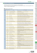
The table below explains the functions allocated to the controller’s I/O signal.Since the signals that can be used vary depending on the controller type and settings, check the signal table for each controller to confirm the available functions.StandardControllers IntegratedMiStandardControllers IntegratedMi StandardClassificationInputOutputSignal abbreviationsCSTRPC1 to PC256BKRLRMOD*STPRESSONHOMEMODEJISLJOG+, JOG−PWRTST0 to ST6TLDCLRPEND/INPPM1 to PM256HENDZONE1PZONERMDS*ALMMOVESV*EMGSMODESWENDPE0 to PE6TLRLSO to LS2LOADTRQSPTP strobe signal (start signal)Command position number signalBrake forced release signalRunning mode switching signalPause signalReset signalServo ON signalHome return signalTeaching mode signalJOG/INCHING switching signalJOG signalTeaching signalStart position commandTorque limit selection signalDeviation counter clear signalIn position signalPositioning complete signalHome return completion signalZone signalPosition zone signalRunning mode status signalController alarm status signalMoving signalServo ON status signalEmergency stop status signalMode status signalWriting complete signalCurrent position number signalTorque limiting signalLimit switch output signalSignalLoad output determination status signalTorque level status signalThis signal can switch the running mode when the MODE switch on the controller is set to AUTO. (AUTO when this signal is OFF, or MANU when the signal is ON)Turning this signal ON resets the alarms that are present. If this signal is turned ON while the actuator is paused (*STP is OFF), the remaining movement can be cancelled.Turning this signal ON performs home-return operation.When the main signal is off, the JOG operation will be conducted for JOG+ and JOG-. When the signal is on, the unit will do the inching operation for JOG+ and JOG-.In the teaching mode, specify a desired position number and then turn this signal ON for at least 20ms to write the current position to the specified position number.While this signal is ON, torque is limited by the value set by a parameter. The TLR signal turns on if torque has reached the specified value.This signal turns ON when the actuator has entered the positioning band after movement. If the actuator has exceeded the positioning band, PEND does not turn OFF, but INP does. PEND and INP can be swapped within parameters.This signal turns ON upon completion of home return.Function descriptionTurns ON when the actuator moves into a position within the range of the target position data that was set. PZONE can be used together with ZONE1, but PZONE is valid only during movement to a specified position.This signal remains ON while the controller is not in the alarm condition, and turns OFF when an alarm has occurred.This signal turns ON when servo is ON.The mode signal input turns it ON when it goes into teaching mode. It turns OFF when it goes into normal mode.This signal turns ON after the controller has completed moving to the target position in the solenoid valve mode.Each signal turns ON when the current actuator position has entered the positioning band before or after the target position. If the actuator has already completed home return, these signals are output even before a movement command is issued or while the servo is OFF.PCON ControllerMiExplanation of I/O Signal Functions■ Signal Function DescriptionInput this signal to cause the actuator to start moving to the position set by the command position number signal.This signal forcibly releases the brake.Turning this signal OFF causes the moving actuator to decelerate to a stop. The actuator will resume the remaining movement if the signal is turned ON during the pause.The servo remains on while this signal is ON, or off while the signal is OFF.Turning this signal ON switches the controller to the teaching mode. (provided that CSTR, JOG+ and JOG- are all OFF and the actuator is not moving).When the JISL signal is off and the JOG +/- signal turns on, the unit will jog in the + (positive) direction when the JOG + turns on and the - (negative) direction when the JOG - turns on.During the JOG operation, the unit slows to a stop when the JOG +/- signal turns off.Turning this signal ON in the solenoid valve mode causes the actuator to move to the specified position. (Start signal is not required)The position deviation counter is continuously cleared while this signal is ON.This signal is used to output the position number achieved at the completion of positioning (binary output)This signal turns ON when the current actuator position has entered the range specified by the parameters.This outputs the operation mode status.Turns ON while the actuator is moving (home return), including when there is push force.This signal remains ON while the controller is not in the emergency stop mode, and turns OFF once an emergency stop has been actuated.This signal remains OFF after the controller has switched to the teaching mode. It turns ON upon completion of data write using the PWRT signal. If the PWRT signal is turned Off, this signal also turns OFF.This signal turns ON once the motor torque has reached the specified value in a condition where torque is being limited by the TL signal.This signal turns ON once the motor torque has reached the specified value. (*PCON-CF dedicated signal)PMEC /AMECPSEP /ASEPROBO NETERC2 PCON ACON SCON PSEL ASEL SSEL XSELTurns ON when the motor current reaches the threshold. (*PCON-CF dedicated signal)Slider TypeRod TypeniniTable/Arm /FlatTypeniGripper/ Rotary TypeLinear Motor TypeCleanroom TypeSplash-ProofControllersPulse MotorServo Motor (24V)Servo Motor (230V)Linear Motor(Note) Signals with asterisks (*) are normally ON and OFF during operation.This signal is used to input a target position number (binary input).PCON 528
