
Page 45 - RoboCilindri, Controller, robocilindri, sinta,
P. 45
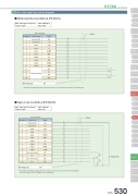
Pulse train input type wiring diagram■ Differential Receiver Method (PCON-PL)PCON ControllerMiStandardControllers IntegratedMiStandardControllers IntegratedMi StandardPIO connectorShieldPin NumberClassificationSignal1External 24V24V2External 0V0V3InputSON4InputTL5InputHOME6InputRES7OutputSV8OutputINP9OutputHEND10Output* ALM11Differential input/PP12PP13/NP14NPMounting plateFG* The shield on the twisted pair cable connected to the pulse connector must be connected to the mounting plate.■ Open Collector Method (PCON-PO)PMEC /AMECPSEP /ASEPROBO NETERC2 PCON ACON SCON PSEL ASEL SSEL XSELPin Number1234567891011121314PIO connectorShieldClassificationExternal 24VExternal 0VInputInputInputInputOutputOutputOutputOutputOpen collector inputN.COpen collector inputN.CSignal24V0VSONTLHOMERESSVINPHEND* ALM/PPPP/NPNPDC24V±10%Mounting plateFG* The shield on the twisted pair cable connected to the pulse connector must be connected to the mounting plate. * Connect the external 0V to the COMMON of the command pulse.PCON 530Slider TypeMax. input pulse frequency : Max. 200 kpps Cable Length : Max. 10mRod TypeniniTable/Arm /FlatTypeMax. input pulse frequency : Max. 60 kpps Cable Length : Max. 2mniGripper/ Rotary TypeLinear Motor TypeCleanroom TypeSplash-ProofControllersPulse MotorServo Motor (24V)Servo Motor (230V)Linear Motor
