
Page 56 - RoboCilindri, Controller, robocilindri, sinta,
P. 56
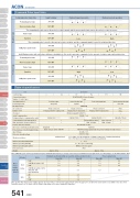
Slider TypeCommand Pulse Input StateCommand pulse train stateOperating methodBackup memoryNumber of I/OSerial CommunicationForward pulse trainReversed pulse trainCommand pulse train input methodPosition detection methodForced release of electromagnetic brakeDielectric strength voltageAmbient operating temperatureAmbient operating atmosphereInput terminalIntegratedPP・/PPNP・/NPPositioner type40-pin connector16 input points/16 output pointsCB-PAC-PIO □□□——During forward operation12-pin connector4 input points / 6 output pointsExternal supply DC24V±10%RS485 1chIncremental encoderDifferential line driverMax. 200 kppsPulse train input type14-pin connector4 input points/4 output pointsCB-PACPU-PIO □□□During reversed operationTable/Arm /FlatTypeRod TypeThe forward pulse train causes the motor to rotate forward, and the reverse pulse train causes the motor to rotate in reverse.Pulse trainSymbolsPP・/PPNP・/NPLowOpen collectorMax. 60 kppsHighThe command pulse is used for the amount of motor rotation, and the command symbol is used for rotational direction.A/B phase pulse trainGripper/ Rotary TypeLinear Motor TypeCleanroom TypeTable of specificationsSplash-ProofConnected actuatorForward pulse trainReversed pulse trainPulse trainSymbolsA/B phase pulse trainItemPP・/PPNP・/NPAn A/B phase pulse with a 90° phase difference (multiplier is 4) is used to generate commands for the amount of rotation and rotational direction.PP・/PPNP・/NPPP・/PPNP・/NPPP・/PPNP・/NPHighSpecificationsLowControllersCCGCYRCA/RCA2/RCL Series ActuatorSolenoid valve typeSerial communication type512 points3 pointsEEPROM—NoneCB-PACY-PIO □□□—Brake release switch ON/OFFON/OFF terminal signal inside the power terminal for brake releasePSASSSXSDC500V 1MΩ0 ~ 40°CWithout corrosive gasesPLPOWeightApprox. 300gApprox. 130gPulse MotorServo Motor (24V)Servo Motor (230V)Linear MotorMotor Power Supply Capacity (Note 2)ActuatorRCA RCA2RCL10W30WMotor20W [Model symbol: 20]20W [Model symbol: 20S] SA4, RA3, TA5Type dedicated2W5W10WStandard specifications/high acceleration and deceleration modelRated [A]1.31.31.31.70.81.01.3Max. [A]4.44.44.45.14.66.46.4Rated [A]1.31.31.31.7Power-saving modelMax. [A]2.52.2ACON Controller MiniStandardControllers IntegratedMiniStandardControllers IntegratedMini StandardController typePMEC Number of control axes/AMECPSEP Positioning Points /ASEPROBO I/O connector NET1-axisExternal DC24V ± 10%SE64 pointsNone— CB-RCB-CTL002 —ERC2 PCON ACON SCONEL EL EL ELI/O powerPeripheral device communication cable Max. input pulse frequency (Note 1) Drive-source cutoff relay at emergency stop Input VoltageVibration resistanceAmbient operating humidity Protection classXYZ directions10 to 57Hz, One side amplitude: 0.035mm (continuous), 0.075mm (intermittent) 58 to 150 Hz 4.9 m/s2 (continuous), 9.8 m/s2 (intermittent)10 - 95% (non-condensing) IP20(Note 1) With the open collector specification, keep the maximum input frequency to 60 kpps or below to prevent malfunction. For applications exceeding 60kpps, use the differential line driver.2.53.4(Note 2) Other than motor power supply capacity, increase 0.5A as control power supply. Inrush current of approx. 5 to 12 times the rated current occurs within 1 to 2 msec from turning the power on. The inrush current changes depending on the power supply line impedance.541 ACONPositive logic Negative logic
