
Page 57 - RoboCilindri, Controller, robocilindri, sinta,
P. 57
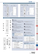
External DimensionsACON-C / CG84 68.1ACON-CY / PL / PO / SEType MiniStandardControllers IntegratedRod TypeMiniStandardControllers IntegratedTable/Arm /FlatTypeMiniStandardGripper/ Rotary TypeLinear Motor TypeCleanroom TypeSplash-ProofControllersPMEC /AMECPSEP /ASEPROBO NETERC2 PCON ACON SCON PSEL ASEL SSEL XSELPulse MotorServo Motor (24V)Servo Motor (230V)Linear Motorø535(80)ø5(80)68.1Name of Each Part55124 6 8These LED colors indicate the condition of the controller.1 LED display35ACON ControllerSlider178.5 170.5120 1123 57 92 PIO connectorConnects a cable for communicating with a PLC orother external equipment.3 Address-setting rotary switchThis switch sets the addresses for controllers usedwhen the unit is linked with controllers.4 Mode switchSwitches between manual teaching pendant operations6 Encoder brake connector Connects the encoder/brake cable for the actuator.7 Brake release switch This switch forces the brake to release.8 Motor connectorConnects the motor cable for the actuator.9 Power terminal blockMain power for controller(s), emergency stopCY/PL/PO Type* PIO connectors are: CY: 12 pinPL/PO: 14 pinSE Type3 4 5 6 7 8 95V ENBL EMGA 24V 0V EMGB 0VTerminal number6 5 4 3 2 1Signal NameBK BK releaseMPI Motor drive-source cutoff terminalMPO Motor drive-source cutoff terminal 24V Positive side of the 24-V power supply0V Negative side of the 24-V power supply EMG EMG signal (application of 24 V)C / CG type125 68 9MANUAL AUTOI/O commands are not accepted. Data can be written from a teaching pendant or PC.I/O commands are valid, while operations from a teaching pendant or PC are not accepted. However, monitoring is possible.C / CG typeTerminalnumber Signal7 S1 6 S2 5 MPI 4 MPO 3 24V 2 0V 1 EMGCY / PL / PO / SE typeNameExternal drive-source cutoff for TP_EMG terminalMotor drive-source cutoff terminal Motor drive-source cutoff terminal Positive side of the 24-V power supply Negative side of the 24-V power supply EMG signal (application of 24 V)Lit (green) Servo ON Lit (red) Alarm activated Unlit Servo OFF Blinking (green) Automatic servo-OFF Emergency stop(MANU) and automatic operations (AUTO). Operation details5 SIO connectorConnects a teaching pendant, PC cable, controller, orgateway unit to a controller.Operation detailsPin No. 1SignalNamePositive side, RS485 differential signal Negative side, RS485 differential signal+5V outputEnable signalEMG line connection to external equipment24-V power for T/PGNDEMG line connection to external equipmentEMG line connection to external equipment groundRemarksFor RS232/485 conversionFor T/PSGA 2 SGBACON 542
