
Page 6 - RoboCilindri, Controller, robocilindri, sinta,
P. 6
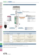
Slider TypeMiniSystem ConfigurationRod TypeTable/Arm /Flat TypeActuatorControllersRCP2 series RCP3 seriesPMEC seriesRCA series RCA2 series RCL seriesAMEC seriesGripper/ Rotary TypeLinear Motor TypeOptionCleanroom TypeSplash-ProofControllersPMECSingle-phase AC115V or Single-phase AC100~240VAMECSingle-phase AC115VI/O Signal TableMotion Pattern2-Position Travel3-Position TravelPin No.Wire ColorSignal TypeSignal NameSignal Name1BrownPIO power24V24V2Red0V0V3OrangeS InputT0 (Solenoid A: ON moves to end position, OFF moves to home position)ST0 (Solenoid A: Move signal 1)4Yellow—ST1 (Solenoid B: Move signal 2)5GreenRES (Alarm reset)RES (Alarm reset)6Blue——7PurpleOutputLS0 (home position detection)/PE0 (home positioning complete)*1LS0 (home position detection)/PE0 (home positioning complete)*18GrayLS1 (end position detection)/PE1 (end positioning complete)*1LS1 (end position detection)/PE1 (end positioning complete)*19WhiteHEND (Homing complete)LS2 (intermediate point detection)/PE2 (intermediate positioning complete)*110Black* ALM (alarm)*2* ALM (alarm)*2Pulse MotorServo Motor (24V)Servo Motor (230V)Linear MotorMEC PC softwareStandardControllers IntegratedMiniStandardControllers IntegratedMini StandardPMEC / AMEC ControllerPLCI/O connectorSupplied with the controllerPIO UnitI/O cable (2m)Supplied with the controllerSee page P486 for maintenance cables.Motor-Encoder Integrated CableSupplied with the actuatorSee page P486 for maintenance cables.PMEC AMECPower cable (2m)Supplied with the controllerEmergency stop switch(At the time of shipment, the EMG connector is short-circuited.)ActuatorPC softwareDownloadCompatible ControllersTeaching Pendant for RoboCylinder(See P483)<Model CON-PT-ENG>PMEC /AMECPSEP /ASEPROBO NETERC2 PCON ACON SCON PSEL ASEL SSEL XSELUSB cable (3m)Supplied with the controller*1: Signals PE0 through PE2 will be output if the pushing motion was enabled in the initial setting. Otherwise, LS0 through LS2 will be output. *2: * ALM is ON when normal, and OFF when it is activated.By using the MEC PC software you can change the stop position data or run a test operation.In addition, you can change the setting on the intermediate stop function, pushing function or change the coordinates.The MEC PC software can be downloaded from the IAI website.479 PMEC / AMECCompleteHOMEBACK POSAccel & Speed Setting FWDPOSMiddleBACKTest run ManualFWDContinuousRUNSTOPNormalReleaseBrakeUSB TeachingPort
