
Page 7 - RoboCilindri, Controller, robocilindri, sinta,
P. 7
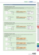
PMEC / AMEC ControllerExplanation of PIO PatternsSlider TypeMiniStandardControllers IntegratedRod TypeMiniStandardControllers IntegratedTable/Arm /Flat TypeMini StandardGripper/ Rotary TypeLinear Motor TypeCleanroom TypeSplash-ProofControllersPMEC /AMECPSEP /ASEPROBO NETERC2 PCON ACON SCON PSEL ASEL SSEL XSELPulse MotorServo Motor (24V)Servo Motor (230V)Linear MotorPIO Pattern (2-position travel)This motion pattern is between two positions, the home position and the end position. The home and end position can be configured numerically (using the MEC PC software or the optional touch panel teaching pendant).Two motions are possible: A positioning motion moves the rod or the slider to the specified position, and a pushing motion presses the rod against a workpiece.PositioningSpeed 50mm/sInput Signal ST0End Position Data PositionSpeed Pushing Force Width30mm 50mm/s(End position)(30mm)Speed 20mm/s(0mm)Solenoid AONmoves at 50mm/s to the end position (30mm position).When ST0 is turned ON, the slider/rod(Home Position)Input Signal ST0Home Position DataSolenoid AOFFPosition Speed Pushing Force Width0mm 20mm/sWhen ST0 is turned OFF, the slider/rod returns to the home position (0mm position) at 20mm/s.PIO Pattern (2-position travel)This motion pattern is between two positions, the home position and the end position, which enables a pushing motion of the rod against a workpiece.PushInput SignalST0 Solenoid A ONWhen the input 0 is turned ON, the actuator moves the rod to the 20mm position at 80mm/s, and from there, pushes it at slower speed to the 30mm position.End Position Data PositionSpeed Pushing Force(End position)30mm 80mm/s 50%Width 10mm(20mm) (30mm)* The pushing motion is performed when there is a numerical value in the controller's push force data. (If there is no numerical value, a positioning motion is performed instead.)PIO Pattern (3-position travel)This motion pattern enables moves between three positions: the end position and the home position, as well as an intermediate position.The positions are switched by combining two signals, ST0 and ST1.Positioning(Home position)(0mm)(10mm)Input SignalST0 Solenoid AST1 Solenoid B OFFWhen only the ST0 is turned ON, the actuatormoves to the starting position at a set acceleration and speed.ONInput Signal (Intermediate position) ST0* By default, you can configure the MEC where you turn both signals OFF to move to theSolenoid A ST1 Solenoid BON*ON* intermediate position, or both ON to stop atthe current position. When both are turned OFF, it stops at the current position.Input SignalST0 Solenoid A OFFST1 Solenoid B ONWhen only ST1 is turned ON, the actuatormoves to the end position at a set acceleration and speed.When both ST0 and ST1 are turned ON, it will move to the intermediate position at the set acceleration and speed.(End position)(30mm)PMEC / AMEC 480
