
Page 89 - RoboCilindri, Controller, robocilindri, sinta,
P. 89
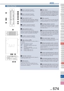
Name of Each Part910 1112121 Motor connector for axis 1 Connect the motor cable of the axis 1 actuator.10 Mode switchThis switch is used to specify the running mode of the controller. The left position indicates the MANU (manual operation) mode, while the right position indicates the AUTO (automatic operation) mode. Teaching can only be performed in manual operation, and automatic operation using external I/Os is not possible in the MANU mode.11 USB connectorA connector for PC connection via USB. If the USBconnector is connected, the TP connector is disabled and all communication inputs to the TP connector are cut off.12 Teaching pendant connectorA half-pitch I/O 26-pin connector that connects a teaching pendant when the running mode is MANU. A special conversion cable is needed to connect a conventional Dsub, 25-pin connector.13 System-memorybackupbatteryconnectorIf you wish to retain the various data recorded in the SRAM of the controller even after the power is cut off, connect the necessary battery to this connector. This battery is installed externally to the unit. The controller does not come standard with the battery (Option).14 Motor power input connectorThis connector is used to input the motor power. It consists of a 2-pin, 2-piece connector by Phoenix Contact.15 Externalregenerativeresistorconnector A connector for the regenerative resistor that must beconnected when the built-in regenerative resistor alone does not offer sufficient capacity in high-acceleration/ high-load operation, etc.Whether or not an external regenerative resistor is necessary depends on the conditions of your specific application such as the axis configuration.16 Controlpower/SysteminputconnectorThis connector is used to connect the control power input, emergency stop switch, and enable switch. It consists of a Phoenix Contact 6-pin 2-piece connector.17 Absolute-databackupbatteryconnectorforaxis1A connector for the battery that backs up absolute data when the actuator uses an absolute encoder. Secure installation of the battery is the customer’s responsibility.18 Absolute-databackupbatteryconnectorforaxis2 A connector for the battery that backs up absolute data when the actuator uses an absolute encoder. Secure installation of the battery is the customer’s responsibility.Type MiniStandardControllers IntegratedRod TypeMiniStandardControllers IntegratedTable/Arm /Flat TypeMini StandardGripper/ Rotary TypeLinear Motor TypeCleanroom TypeSplash-ProofControllersPMEC /AMECPSEP /ASEPROBO NETERC2 PCON ACON SCON PSEL ASEL SSEL XSELPulse MotorServo Motor (24V)Servo Motor (230V)Linear Motor134 Encoder connector for axis 1 Connect the encoder cable of the axis 1 actuator.5 Brake switch for axis 2This switch is used to release the axis brake.Setting it to the left position (RLS side) forcibly releases the brake, while setting it to the right position (NOM side) causes the controller to automatically control the brake.6 Encoder connector for axis 2 Connect the encoder cable of the axis 2 actuator.7 Status indicator LEDsThese LEDs are used to indicate the operating condition of the controller.The LED status indicators are as follows:1415 1618 178 Panel unit connectorA connector for the panel unit (optional) that displays the controller status and error codes.9 I/O ConnectorA connector for interface I/Os.34-pin flat cable connector for DIO (24IN/8OUT) interface.I/O power is also supplied to the controller via this connector (Pin No. 1 and No. 34).2 Motor connector for axis 23 Connect the motor cable of the axis 2 actuator. 45 63 Brake switch for axis 1This switch is used to release the axis brake. Setting it to the left position (RLS side) forcibly releases the brake, while setting it to the right position (NOM side) causes the7 controller to automatically control the brake. 8PWR : RDY :ALM : EMG :SV1 :SV2 :Power is input to controller.The controller is ready to perform program operation.The controller is abnormal.An emergency stop is actuated and the drive source is cut off.The axis 1 actuator servo is on.The axis 2 actuator servo is on.ASEL ControllerSliderASEL 574
