
Page 17 - RoboCilindri, RCP4, robocilindri, sinta,
P. 17
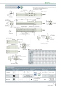
DimensionsCAD drawings can be downloaded from our website. www.robocylinder.de2D CADRCP6 RoboCylinder *1 When the slider is returning to its home position, please be careful of interference fromφ8 φ4.5Reference surface31 (φ5H7 pitch ±0.02)60 50110 37.5 3Home M.E.position for allowable moment calculationM.E.3 S.E.58 42Reference surface (B dimensions range)517.5 38.5 57 58H-φ4.5, φ8 deep counterbored, depth 4.5 (From back side)30E-M5 through(Bolt screw-in depth: 10)(0.5)Details of base mounting holesLM-φ4 H7 depth 5.5 (From mounting surface)9150.5 (Without brake) 190 (With brake)CJTTop29.4 4CJB BottomN-oblong hole depth 5.5 (From mounting surface)PG×100PJ (φ4 hole - oblong hole)K (φ4 hole - φ4 hole) D×100PB9.5 Teaching port2-M3 depth 6 (For ground line)13StrokeA112.5 (Without brake) 152 (With brake)2-φ5 H7 reamed, depth 6 4-M5 depth 10M.E: Mechanical end 32 ±0.02S.E: Stroke endMust be 100 or moresurrounding objects, as it will travel until it reaches the M.E.26 165.54.521 50 20.161(1.5)35.531 23+0.010 4016.5 464.95 2862.5 Top face of slider33 2561(1.5)402-M3 depth 6 (For ground line)(R2)Detail view of PRCP6S-SA6CStatus LED6510 25Unavailable when CJL is selected.CJL LeftCJT Top32CJB Bottom2-M3 depth 6 (For ground line)CJRRightUnavailable when CJR is selected.Unavailable 20 when CJL isselected. CJL LeftActuator Center2-M3 depth 6 (For ground line)CJRRightUnavailable when CJR is selected.ABDEGHJKMN 0111111111111111Cable exit direction (Option)Applicable Controllers2.0 2.2 2.3 2.5 2.7 2.8 3.0 3.2 3.4 3.5 3.7 3.9 4.1 4.2 4.4 4.6 2.2 2.4 2.6 2.8 2.9 3.1 3.3 3.4 3.6 3.8 4.0 4.1 4.3 4.5 4.6 4.8 2.1 2.3 2.5 2.6 2.8 3.0 3.2 3.3 3.5 3.7 3.9 4.0 4.2 4.4 4.6 4.7 2.4 2.5 2.7 2.9 3.1 3.2 3.4 3.6 3.8 3.9 4.1 4.3 4.4 4.6 4.8 4.9Must be 100 or more58 24 164Cable exit direction (Option)Connector for power supply/I/O cable connectionDimensions and Mass by StrokeStrokeRCP6 w/obrakew/brake RCP6S w/obrakew/brake150 200 250 300 350 400 450 500 550 600 650 700 750 800 423 473 523 573 623 673 723 773 823 873 923 973 1023 1073 462.5 512.5 562.5 612.5 662.5 712.5 762.5 812.5 862.5 912.5 962.5 1012.5 1062.5 1112.5 461 511 561 611 661 711 761 811 861 911 961 1011 1061 1111 500.5 550.5 600.5 650.5 700.5 750.5 800.5 850.5 900.5 950.5 1000.5 1050.5 1100.5 1150.5 310.5 360.5 410.5 460.5 510.5 560.5 610.5 660.5 710.5 760.5 810.5 860.5 910.5 960.5 272 322 372 422 472 522 572 622 672 722 772 822 872 9220112233445566778 4 6 6 8 8 1010121214141616181820 1122334455667788 4 4 6 6 8 8 10101212141416161818 0 85 85 185185285285385385485485585585685685785 0 100 100 200 200 300 300 400 400 500 500 600 600 700 700 800 2333333333333333Lw/obrake Mass RCP6 w/brake (kg) RCP6S w/obrake w/brake50 100 323 373 362.5 412.5 361 411 400.5 450.5 210.5 260.5 172 222The RCP6 series actuators can be operated by the controllers indicated below. Please select the type depending on your intended use. * Please refer to P.147 for more information about the built-in controller of RCP6S series.NamePCON-CB/CGBMCON-C/CGExternal viewMax. number of controlled axes1 4 4Input powerDC24VPositioner*OptionPulse train*OptionControl method Program-Network *OptionMaximum number of positioning points512(768 for network spec.)256 30000Reference pagePlease see P.132Please see the MCON catalog or manual.Single-phase 100~230VACwill vary depending on the controller.Please refer to reference page for more information.Please see the MSEL-PC/PG catalog or manual.This model is network-compatible only.Note:· The type of compatible networksMSEL-PC/PG* Please select "high-output speci cation" as an option for the MCON. With the MCON, operation is possible only when the high-output speci cation is selected.- -RCP6(S)-SA6C 16
