
Page 19 - RoboCilindri, RCP4, robocilindri, sinta,
P. 19
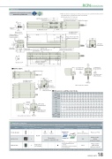
DimensionsCAD drawings can be downloaded from our website. www.robocylinder.de2D CADRCP6 RoboCylinder *1 When the slider is returning to its home position, please be careful of interference fromφ9.5 φ6Reference surface(1)Details of base mounting holes39 (φ5H7 pitch ±0.02) (87.5) L140 (Without brake) 190 (With brake)Range of 87.5 or more Pay attention to interference. (5)17.5 2638.5 73 17.6 18.535.523374840167.5 Top face of+0.010 slider (5.5) 5.3 40 19.5 4835.5 21735.5 5.5position for allowable moment calculationReference surface (B dimensions range)133 S.E.StrokeAE-M5 through(Bolt screw-in depth: 10)130 59 3Home M.E.70 5Detail view of PPRCP6S-SA7C25Unavailable when CJL is selected.CJL LeftCJT 3226.5 51.5M-φ4 H7 depth 6H-φ6, φ9.5 deep counterbored, depth 5.5 (From back side)2-M3 depth 6 (For ground line)2-M3 depth 6 (For ground line)CJR RightUnavailable when CJR is selected.Cable exit direction (Option)Applicable ControllersM.E.68 42N-oblong hole depth 6 68 (Frommountingsurface)(From mounting surface)Status LEDMust be 100 or more68 4016.5 Teaching port2-M3 depth 6 (For ground line)165 (Without brake) 215 (With brake)Unavailable 20 when CJL isselected.CJL LeftCJB BottomCJB BottomMass2-φ5 H7 reamed, depth 10 80surrounding objects, as it will travel until it reaches the M.E. M.E: Mechanical end S.E: Stroke end4-M5 depth 10 65 42 ±0.02Work part installed on the slider. Pay attention to interference.Must be 100 or more(R2)G×100P 45 J (φ4 hole - oblong hole)K (φ4 hole - φ4 hole)D×100P 80309B TopConnector for powersupply/I/O cable connection Dimensions and Mass by StrokeCJT A Top B0112233445566778 4 6 6 8 8 10 10 12 12 14 14 16 16 18 18 20 11223344556677884002 2 3 3 3 3 3 3 3 3 3 3 3 3 3 329.42-M3 depth 6DEGHJKMN 0111111111111111(For ground line)CJR RightUnavailable when CJR is selected.4 6 6 8 8 10 10 12 12 14 14 16 16 18 18 85 85 185 185 285 285 385 385 485 485 585 585 685 685 785 0 100 200 200 300 300 400 400 500 500 600 600 700 700 800The RCP6 series actuators can be operated by the controllers indicated below. Please select the type depending on your intended use. * Please refer to P.147 for more information about the built-in controller of RCP6S series.NamePCON-CB/CGBMCON-C/CGExternal viewMax. number of controlled axes1 4 4Input powerDC24VPositioner*OptionPulse train*OptionControl method Program-Network *OptionMaximum number of positioning points512(768 for network spec.)256 30000Reference pagePlease see P.132Please see the MCON catalog or manual.Single-phase 100~230VACwill vary depending on the controller.Please refer to reference page for more information.Please see the MSEL-PC/PG catalog or manual.This model is network-compatible only.Note:· The type of compatible networksMSEL-PC/PG* Please select "high-output speci cation" as an option for the MCON. With the MCON, operation is possible only when the high-output speci cation is selected.- -Cable exit direction (Option)Stroke 50 100 150 200 250 300 350 400 450 500 550 600 650 700 750 800RCP6 w/obrake 392 442 492 542 592 642 692 742 792 842 892 942 992 1042 1092 1142 L w/brake 442 492 542 592 642 692 742 792 842 892 942 992 1042 1092 1142 1192 RCP6S w/obrake 417 467 517 567 617 667 717 767 817 867 917 967 1017 1067 1117 1167 w/brake 467 517 567 617 667 717 767 817 867 917 967 1017 1067 1117 1167 1217 252 302 352 402 452 502 552 602 652 702 752 802 852 902 952 1002 188 238 288 338 388 438 488 538 588 638 688 738 788 838 888 938RCP6 w/obrake 3.6 3.8 4.0 4.3 4.5 4.7 4.9 5.2 5.4 5.6 5.9 6.1 6.3 6.5 6.8 7.0 w/brake 4.0 4.2 4.5 4.7 4.9 5.1 5.4 5.6 5.8 6.1 6.3 6.5 6.7 7.0 7.2 7.4 (kg) RCP6S w/obrake 3.8 4.0 4.2 4.4 4.7 4.9 5.1 5.3 5.6 5.8 6.0 6.3 6.5 6.7 6.9 7.2 w/brake 4.2 4.4 4.6 4.9 5.1 5.3 5.6 5.8 6.0 6.2 6.5 6.7 6.9 7.1 7.4 7.6RCP6(S)-SA7C 18
