
Page 45 - RoboCilindri, RCP4, robocilindri, sinta,
P. 45
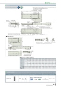
DimensionsCAD drawings can be downloaded from our website. 2DRCP6 RoboCylinder *1 When the slider is returning to its home position, please be careful of interference fromwww.robocylinder.deCADsurrounding objects, as it will travel until it reaches the M.E.position for allowable moment calculationReference surface 1156 (Slider width) 150118(123)158160 (Base width)258Must be 100 or moreM3 depth 6(For ground line)276.4 (Without brake, with brake)6-M8 depth 16P-φ8H7 reamed From base mounting surface depth 9 R-oblong hole From base mounting surface depth 9RCP6S-WSA16RG (H)9100J×100 pitch 55(1)100±0.02 (n/a for 50&100mm strokes)R-oblong hole From base mounting surface depth 9(59.6) 97(8.4) Q (n/a for 50&100mm strokes)70.514170.544 Stroke5 1105M.E. S.E.T-slot : M3 (both sides)90 405555Status LEDQ (n/a for 50&100mm strokes)N±0.02 (n/a for 50&100mm strokes) 55P-φ8H7 reamed From base mounting surface depth 9K-φ9 through -φ16.5 counterbored (From opposite side)CJO OutsideA72 Home M.E.49.5LM.E: Mechanical end 2-φ8H7 reamed, depth 8S.E: Stroke end 4-M8 depth 24.520036.57 59134 (φ8H7 pitch: ±0.02)25836.539 22.87 593.3 5.8140+ +0.015 8036.575 49.56 38.51 713 36.5Must be 100 or moreM3 depth 6(For ground line)336.4 (Without brake, with brake)6-M8 depth 16CJO Outside(8.4)Teaching portConnector for power supply/I/O cable connection70.514170.5Applicable ControllersCable exit direction (Option) side-mounted to the left (ML).Dimensions and Mass by StrokeStroke LAGHJKN50 100 150 200 250 300 350 400 450 500 550 415.5 465.5 515.5 565.5 615.5 665.5 715.5 765.5 815.5 865.5 915.5 366 416 466 516 566 616 666 716 766 816 866- - 100 100 100 100 100 100 100 100 100 158 208 58 108 58 108 58 108 58 108 58600 650 700 750 800 850 900 950 1000 1050 1100 965.5 1015.5 1065.5 1115.5 1165.5 1215.5 1265.5 1315.5 1365.5 1415.5 1465.5 916 966 1016 1066 1116 1166 1216 1266 1316 1366 1416 100 100 100 100 100 100 100 100 100 100 100 108 58 108 58 108 58 108 58 108 58 108Cable exit direction (Option)φ9Details of base mounting part3 1.3Side T-slot details0 0 1 1 2 2 3 3 4 4 5 5 6 6 7 7 8 8 9 9 10 10 4 4 8 8 10 10 12 12 14 14 16 16 18 18 20 20 22 22 24 24 26 26 - - 100 100 100 100 100 100 100 100 100 100 100 100 100 100 100 100 100 100 100 100P 1122222222222222222222 Q - - 208 258 308 358 408 458 508 558 608 658 708 758 808 858 908 9581008105811081158 R 0011111111111111111111RCP6 w/obrake 10.4 11.0 11.6 12.2 12.7 13.3 13.9 14.5 15.1 15.7 16.3 16.9 17.5 18.1 18.7 19.3 19.9 20.5 21.0 21.7 22.2 22.8 w/brake 10.6 11.2 11.8 12.4 13.0 13.6 14.2 14.8 15.4 16.0 16.6 17.2 17.7 18.3 18.9 19.5 20.1 20.7 21.3 21.9 22.5 23.1 (kg) RCP6S w/obrake 10.6 11.2 11.8 12.4 13.0 13.6 14.2 14.8 15.4 16.0 16.6 17.2 17.7 18.4 18.9 19.5 20.1 20.7 21.3 21.9 22.5 23.1 w/brake 10.9 11.5 12.1 12.7 13.3 13.9 14.4 15.0 15.6 16.2 16.8 17.4 18.0 18.6 19.2 19.8 20.4 21.0 21.6 22.2 22.7 23.4MassThe RCP6 series actuators can be operated by the controllers indicated below. Please select the type depending on your intended use. * Please refer to P.147 for more information about the built-in controller of RCP6S series.Name External Max. number of ZU_RCP6-WSA16R view controlled axesPCON-CFB/CGFB 1Input powerDC24VControl methodMaximum number Reference page of positioning points512 Please see P.132 (768 for network spec.)Positioner Pulse train Program - *Option *OptionNetwork *OptionRCP6(S)-WSA16R 44
