
Page 109 - RoboCilindri, Controller, robocilindri, sinta,
P. 109
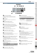
Part NamesK type (General)XSEL ControllerMi1 FG Connection TerminalA terminal for connecting to the FG terminal on the enclosure. The PE of the AC input are connected to the enclosure inside the controller.2 Fuse HolderThis is the single-pole fuse holder for overcurrent protection inthe AC input.3 Main Power Input ConnectorThis connector is for the AC230V single-phase input.4 Regeneration Resistance Unit ConnectorThis connector is for the regenerative resistance unit (optional/REU-1) that is connected when there is insufficient capacity with the built-in regenerative resistor for high-acceleration/high-loads, etc.5 Motor Cable ConnectorA connector for the motor power-supply cable of the actuator.6 Actuator Sensor Input ConnectorA connector for axis sensors such as LS, CREEP and OT.7 Absolute-data backup batteryThis is the encoder backup battery unit when an absolute encoder is used.This battery is not connected for a non-absolute axis.8 Brake Release Switch (Brake-equipped specification only)Locking toggle switch for releasing the axis brake. Pull the switch forward and then tilt it up or down.Set the switch to the top position (RLS) to forcibly release the brake, or to the bottom position (NOM) to have the brake automatically controlled by the controller.9 Axis Driver Status LEDThis LED is for monitoring the operating status of the driver CPU that controls the motor drive.Features the following three LEDs.11 System I/O ConnectorA connector for three input/output points including two inputs used tofor the controller operation, and one system status output.StandardControllers IntegratedMiStandardControllers IntegratedMi StandardNameEMG Emergency stop input ENBRDYON=operation enabled, OFF=emergency stop ON=operation enabled, OFF=servo OFFThis signal outputs the status of this controller. Cascade connection is supported. Short=ready, Open=not readySafety Gate InputSystem Ready Relay Output12 I/O 24V Power Connector16 , 17 This connector is for supplying external I/O power to theinsulator when DIs and DOs are installed in the I/O boards.13 Panel WindowThis window has a 4-digit, 7-segment LED and PSEPPMEC /AMEC/ASEPROBO NETERC2 PCON ACON SCON PSELfive LED lamps showing the system status.14 Mode switchThis is a locking toggle switch for designating the controller operating mode. Pull the switch forward and then tilt it up or down.The top position indicates the MANU (manual operation) mode, while the bottom position indicates the AUTO (automatic operation) mode.Teaching can only be performed in manual operation,and automatic operation using external I/Os is not possible in the MANU mode.15 Teaching Connector ASELThis is a 25-pin D-sub connector for connecting a teaching pendant or PC cable to enter programmed positions.16 Standard I/O Slot (Slot 1)A 32-point input / 16-point output PIO board is installed as standardequipment.17 Expansion I/O Slots (Slot 2, Slot 3, Slot 4) Install an expansion I/O board. (Option)SSEL XSELNameALM SVON BATT ALMColorOrangeFunction descriptionIndicates when an error has been detected by the driver. Indicates that the servo is ON and the motor is driven. Indicates low absolute battery charge.GreenOrange10 Encoder sensor cable connector 15-pin D-sub connector for the actuator encoder cable.XSEL 594Slider TypeRod TypeniniTable/Arm /FlatTypeniGripper/ Rotary TypeLinear Motor TypeCleanroom TypeSplash-ProofControllersPulse MotorServo Motor (24V)Servo Motor (230V)Linear Motor
