
Page 110 - RoboCilindri, Controller, robocilindri, sinta,
P. 110
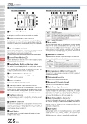
StandardControllers Integrated12 131417 18 19XSEL Controller SliderType MiniPart NamesP type (4-axis)Q type (Absolute, brake unit + expansion base, 6-axis)5610 11Rod4 3TypeMini3 24561011121416StandardControllers IntegratedTable/Arm /FlatTypeMini StandardGripper/ Rotary TypeLinear Motor TypeCleanroom TypeSplash-ProofControllersPMEC /AMECPSEP /ASEPROBO NETERC2 PCON ACON SCON PSEL ASEL SSEL XSELPulse MotorServo Motor (24V)Servo Motor (230V)Linear Motor595 XSEL179 15 132 11 FG Connection Terminal9 157 8A terminal for connecting to the FG terminal on the enclosure. The PE of the AC input are connected to the enclosure inside the controller.2 External regeneration unit connectorA connector for the regenerative resistor that must be connected when the built-in regenerative resistor alone does not offer sufficient capacity in high-acceleration/ high- load operation, etc. Whether or not an external regenerative resistor is necessary depends on the conditions of your specific application such as the axis configuration.3 AC Power Input ConnectorAC230V 3-phase input connector. It consists of six terminals includingmotor power-supply, control power-supply and PE terminals.Standard equipment only includes a terminal block.Due to risk of electrical shock, do not touch this connector while power is supplied.4 Control Power Monitor LEDA green light illuminates while the control power supply is properlygenerating internal controller power.5 Enable/Disable Switch for Absolute BatteryThis switch is for enabling/disabling the encoder backup using the absolute data backup battery. The encoder backup has been disabled prior to shipment. After connecting the encoder/axis-sensor cables, turn on the power, and then set this switch to the top position.6 Encoder/Axis Sensor ConnectorA connector for axis sensors such as LS, CREEP and OT.* LS, CREEP, and OT are options.7 Motor connectorA connector for driving the motor in the actuator.8 Teaching Pendant Type Selection SwitchThis switch is for selecting the type of teaching pendant to connect to the teaching connector. Switch between an IAI standard teaching pendant and the ANSI-compatible teaching pendant. Operate the switch on the front face of the board in accordance with the teaching pendant used.9 Teaching ConnectorThe teaching interface is used for connecting the IAI teaching pendantor the software on a PC to operate and configure the system, etc.10 System I/O connectorA connector for managing the safety operation functions of the controllers. Controllers of the global specification let you configure a safety circuit conforming to safety categories of up to 4 using this connector and an external safety circuit.11 Panel WindowThis window consists of a 4-digit, 7-segment LED and five LED lampsshowing the system status.Name Status when LED is litRDY CPU Ready (programs can be run)ALM CPU Power (System Down Level Error) CPU Hardware Problem EMG Emergency stop status, CPU hardware problem,or power system hardware problem PSE Power supply hardware problem CLK System clock problem12 Mode switchThis is a locking toggle switch for designating the controller operating mode. Pull the switch forward and then tilt it up or down. The top position indicates the MANU (manual operation) mode, while the bottom position indicates the AUTO (automatic operation) mode. Teaching can only be performed in manual operation, and automatic operation using external I/Os is not possible in the MANU mode.13 Standard I/O connector50-pin flat connector structure, comprised of 32 input / 16 output DIOs. Overview of Standard I/O Interface SpecificationsDescription of five LEDsItem Connector Name Applicable connector Power Supply Input Output Connected toDetailsI/O50-Pins, Flat ConnectorPower is supplied through connector pins No. 1 and No. 50. 32 points (including general-purpose and dedicated inputs) 16 points (including general-purpose and dedicated inputs) External PLC, sensors, etc.14 General-purpose RS232C Port ConnectorThis port is for connecting general-purpose RS232C equipment.(2-channels are available)15 Field network board slotA slot that accepts a fieldbus interface module.16 Expansion I/O Board (optional) Slots that accept optional expansion I/O boards.17 Brake Power Input ConnectorA power input connector for driving the actuator brake. DC 24V must be supplied externally. If this power supply is not provided, the actuator brake cannot be released. Be certain that power is supplied to the brake-equipped axis. Use a shielded cable for the brake power cable, and connect the shielding on the 24V power supply side.18 Brake Release Switch ConnectorA connector for the switch that releases the actuator brake externally to the controller. Shorting the COM terminal and BKMRL* terminal of this connector will release the brake. Use this method if you wish to manually operate the actuator after the controller has experienced a power failure or malfunction.19 Brake SwitchLocking toggle switch for releasing the axis brake. Pull the switch forward and then tilt it up or down. Setting it to the top position (RLS side) forcibly releases the brake, while setting it to the bottom position (NOM side) causes the controller to automatically control the brake.
